Section IV - Operating Procedures
Quincy Compressor
®
- QSB/T
™
21
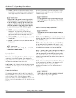
Menu 02 - Filter Service Hours
LED 1 -
Separator service hours setup. The display shows
the hours remaining, alternating with
SEPA
. On servicing
the separator, set the counter to the desired service
interval.
LED 2 -
Air filter service hours setup. The display shows
the hours remaining, alternating with
AIr.F
. On servicing
the air filter, set the counter to the desired service interval.
An
A
will blink at the left side of the display on time-out.
LED 3 -
Fluid filter service hours setup. The display
shows the hours remaining, alternating with
FLu.F
. Use
UP
or
DOWN
to adjust the value to the desired range. An
F
will blink at the left side of the display on time-out.
LED 4 -
Fluid sample/service hours setup. The display
shows the hours remaining, alternating with
FLu
. On
servicing the fluid filter or taking a sample, reset the
counter to the desired service interval.
The LED’s described above, will blink when the service
intervals reach
00
in the main running display. All
settings are saved when the display reading is steady.
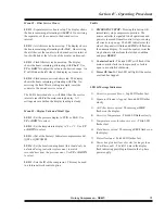
Menu 03 - Display Units and Model Type
LED 1 -
Set the pressure display to PSIG or BAR. Use
UP
or
DOWN
to select.
LED 2 -
Set the temperature display to °F or °C. Use
UP
or
DOWN
to select.
LED 3 -
(Set at the Factory) Indicates compressor model
(QSF or QSB/QMB).
LED 4 -
Set the (total) running hours
(this should only be
adjusted during controller replacement, to match
recorded time from the previous one.)
Use
UP
or
DOWN
to select.
LED 5 -
Sets the ID of the compressor. This may be used
in a future network control option.
Faults
1)
EMERGENCY STOP -
Pressing this button will
immediately stop compressor operation. The
microcontroller is signaled to halt operations and
power is removed from all control relays; causing
all circuits to open up. The LED indicators at the
side of the panel will flash and
STOP
will flash on
the numeric display. To reset the control, twist the
stop button to release from the latched condition
and press
RESET.
2)
Contactor Fault -
The side LED’s will flash if the
main contactor fails to close properly or fails to
open in a controlled shutdown.
3)
Motor OL/Fault -
This LED will light if the motor
overload has tripped.
LED & Message Indicators
1)
Excessive pressure Error -
Top LED flashes fast.
2)
Separator Element clogged -
Second LED flashes
slowly.
3)
Air Filter timer expired -
The message
AIRF
flashes on the display.
4)
Excessive Temperature -
Third LED flashes slowly.
5)
Temperature error (broken wire etc.) -
Third LED
flashes fast.
6)
Fluid timer expired -
The message
FLUI
flashes on
the display.
7)
Motor Overload -
Forth LED flashes fast.
8)
Power line glitches (loss of cycles for longer than
40 milliseconds) -
The left 3 bars in the display
flash indicating possible problems in the 3-phase
power supply.
Summary of Contents for QSB Series
Page 2: ......
Page 9: ...Section I General Quincy Compressor QSB T 5 MODEL IDENTIFICATION...
Page 21: ...Quincy Compressor QSB T 17 THIS PAGE INTENTIONALLY LEFT BLANK...
Page 27: ...Quincy Compressor QSB T 23 THIS PAGE INTENTIONALLY LEFT BLANK...
Page 71: ...Quincy Compressor QSB T 67 THIS PAGE INTENTIONALLY LEFT BLANK...
Page 72: ...Appendix A Dimensional Drawings 68 Quincy Compressor QSB T QSB 15 50 HP air cooled...
Page 73: ...Appendix A Dimensional Drawings Quincy Compressor QSB T 69 QSB 15 50 HP water cooled...


