Section VI - Servicing
Quincy Compressor
®
- QSB/T
™
31
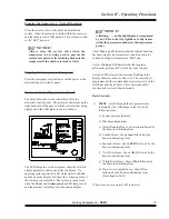
Using the Belt Tension Tester (P/N 142645)
1)
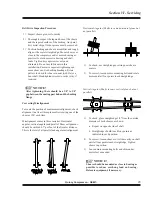
Measure the span length (t).
2)
Position the large o-ring using either of the
following methods:
(a.) On the scale reading “Inches,” set the o-ring to
show a deflection equal to 1/64" per inch of
span length (t).
(b.) On the scale reading “Inches of Span Length,”
set the o-ring to show a deflection equal to the
inches of measured span length (t).
(Read
scales at the bottom edge of o-ring. Set the
small o-ring at “0” pounds.)
3)
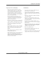
Always rotate pulleys a minimum of 2 revolutions
before taking belt tension measurements. At center
of span (t) apply force, with belt tension tester
perpendicular to the span, large enough to deflect
one belt on the drive until the bottom edge of the
large o-ring is even with the tops of the
remaining belts.
(A straight edge across
the belt tops will assure accuracy of
positioning
.)
4)
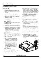
Find amount of deflection force on the
upper scale of the tension tester. The
sliding rubber o-ring slides up the scale
as tool compresses - stays up for
accurate reading of pounds pressure.
Read at bottom edge of ring.
(Slide the
o-ring to back to “0” pounds before
reusing.)
5)
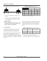
Compare deflection force with range of
forces listed for unit being tested. If
less than minimum recommended
deflection force, tighten belts. If more
than the maximum recommended
deflection force, drive is too tight.
6)
Check tension of each belt on the drive
as described above.
7)
Check the ride height. All belts in each
set must ride at the same height in the
pulley groove within 0.030" total of
each other.
8)
Recheck for pulley misalignment and correct as
necessary. Retension after adjusting.
9)
Operate the compressor for a few minutes to seat
the belts in the sheave grooves. Observe the
operation of the drive during start-up and full load
operation (highest load conditions). A slight bowing
of the slack side of the drive indicates adequate
tension. Excessive bowing or slippage indicates
insufficient tension. If the slack side remains taut
during the highest load the drive is too tight.
10)
(15-30 HP units)
Assure that motor base is level
when belts are at initial tension. If motor base is
level, belt tensioning is complete. If not, refer to
motor base instructions in appropriate instruction
manual, level motor base and repeat tensioning
procedure.
Summary of Contents for QSB Series
Page 2: ......
Page 9: ...Section I General Quincy Compressor QSB T 5 MODEL IDENTIFICATION...
Page 21: ...Quincy Compressor QSB T 17 THIS PAGE INTENTIONALLY LEFT BLANK...
Page 27: ...Quincy Compressor QSB T 23 THIS PAGE INTENTIONALLY LEFT BLANK...
Page 71: ...Quincy Compressor QSB T 67 THIS PAGE INTENTIONALLY LEFT BLANK...
Page 72: ...Appendix A Dimensional Drawings 68 Quincy Compressor QSB T QSB 15 50 HP air cooled...
Page 73: ...Appendix A Dimensional Drawings Quincy Compressor QSB T 69 QSB 15 50 HP water cooled...


