Section II - Description
Quincy Compressor
®
- QSB/T
™
7
Air Flow
When the compressor is operating, a partial vacuum is
produced at the compressor inlet. Air entering via the air
filter flows through the inlet valve into the rotor housing
where it is compressed, then discharged into the air/fluid
reservoir. Compressed air passes through the complete
system, then through a minimum pressure check valve to
the service connection.
Cooling System
Fluid Coolers
Fluid coolers may use either air or water as a cooling
medium. The following descriptions point out the major
differences between the two types of coolers.
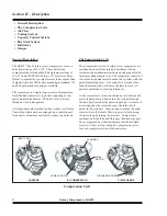
Air-cooled Fluid Coolers
The air-cooled fluid cooler and aftercooler are finned
aluminum tube, one piece design. Ambient air is forced
through the fins by a motor driven fan, cooling the fluid
and air in the tubes. To maintain proper compressor
operation, the ambient air temperature should not exceed
the temperatures listed in Appendix B - Technical Data.
The cooler fins must be kept clean at all times. Fluid
leaving the receiver passes through a thermal mixing
valve before traveling on to the cooler. The purpose of
the thermal valve is to maintain a minimum fluid
discharge temperature at the compressor of approximately
180°F.
Water-cooled Fluid Coolers
Water-cooled fluid coolers are of the shell and tube
design. Fluid passes through the shell transferring its heat
to the water flowing through the tubes. Fluid leaving the
cooler does not pass through a thermal mixing valve as in
an air-cooled unit, but goes directly to
t
he fluid filter and
the compressor. Fluid discharge temperature at the
compressor is maintained by a water temperature
regulating valve located in the discharge water line. The
water temperature regulating valve uses a probe to sense
fluid temperature and opens and closes, governing water
flow through the cooler.
Aftercoolers
Aftercoolers reduce the amount of water in the discharge
air. They are used to lower the temperature of the
discharge air thereby condensing water vapor from the
compressed air. This allows most of the contained water
to be trapped and expelled from the unit, reducing water
related problems downstream.
Air-cooled aftercoolers are part of the air-cooled fluid
cooler. Cooling air from the fan is blown through the
aftercooler and the fluid cooler.
Water-cooled aftercoolers are placed in series with the
fluid cooler. Incoming water is first directed through the
aftercooler and then on to the fluid cooler.
Moisture Separator
A combination moisture separator and water trap is
provided for collecting and expelling water to the
customer’s drain.
Summary of Contents for QSB Series
Page 2: ......
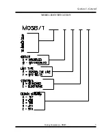
Page 9: ...Section I General Quincy Compressor QSB T 5 MODEL IDENTIFICATION...
Page 21: ...Quincy Compressor QSB T 17 THIS PAGE INTENTIONALLY LEFT BLANK...
Page 27: ...Quincy Compressor QSB T 23 THIS PAGE INTENTIONALLY LEFT BLANK...
Page 71: ...Quincy Compressor QSB T 67 THIS PAGE INTENTIONALLY LEFT BLANK...
Page 72: ...Appendix A Dimensional Drawings 68 Quincy Compressor QSB T QSB 15 50 HP air cooled...
Page 73: ...Appendix A Dimensional Drawings Quincy Compressor QSB T 69 QSB 15 50 HP water cooled...


