Section IV - Operating Procedures
Quincy Compressor
®
- QSB/T
™
19
Stopping the Compressor - Normal Operation
Close the service valve to the plant air distribution
system. Allow the pressure to build within the reservoir
and the compressor to fully unload. Turn selector switch
to the “OFF” position.
NOTICE!
Always close the service valve when the
compressor is not being used to prevent the
system’s air pressure from leaking back into the
compressor if the check valve leaks or fails.
Stopping the Compressor - Emergency
Press the emergency stop button or cut the power at the
main disconnect switch or panel.
Electronic Control Operation (optional)
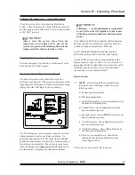
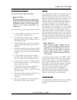
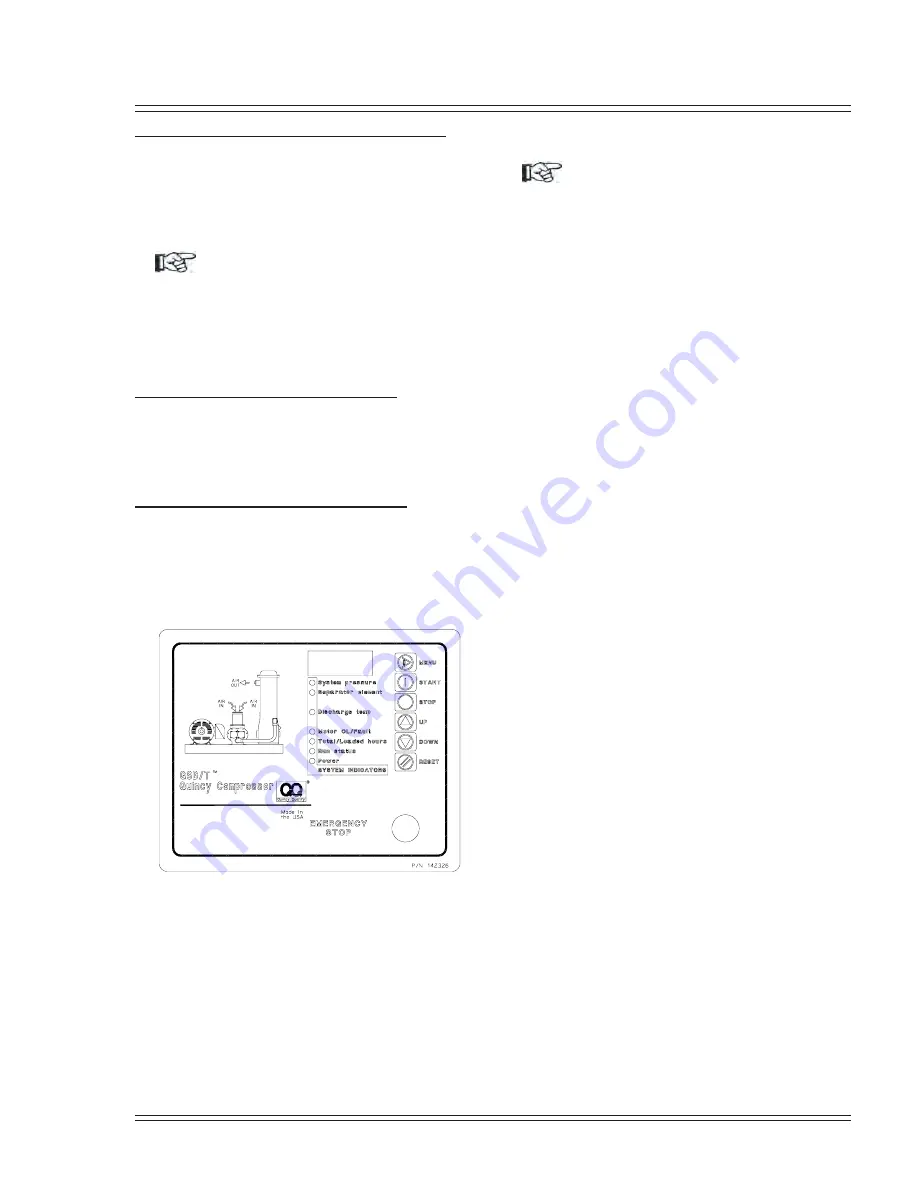
The decal below shows the control layout for the
electronic control panel. The primary controls are on the
right hand side of the panel, with the selected item being
displayed on the LED digits in the top window.
The LED lamps in a vertical column, show the selected
display parameter and/or any alarm conditions. On
applying system power the LED status lights will blink
and the numeric display will show the version number of
the software code installed. The system is ready to run
when the
Power
and
System pressure
LED lamps are lit
and the pressure is displayed in the numeric display.
NOTICE!
A flashing —— on the digit display, accompanied
by an LED on the left, signifies a faulty sensor
(either the pressure transducer or the temperature
probe).
A fast blinking LED indicates that the labeled function
has been tripped; an overpressure condition or motor
overload or high air temperature (HAT) trip.
A slow blinking LED indicates that the separator
differential pressure (DP) switch has been tripped.
A steady LED, along with a message blinking on the
display, indicates a service time-out. The controller is
programmed with recommended service intervals on the
fluid filter and the air filter. These filters should be
checked and serviced when indicated.
Basic Controls
1)
MENU
- scrolls through the set parameters as
indicated by the LED lamps to the left, in the
following order:
a) System pressure (default)
b) Discharge temperature
c) (Total) Running Hours - shows
run
followed by
the hours in alternating form.
d) Loaded Hours - shows
load
followed by the
hours in alternating form.
e) Separator Hours - shows
SEPA
followed by the
hours in alternating form.
f) *Air Filter Hours - shows
AIr.f
followed by the
hours in alternating form.
g) *Fluid Filter Hours - shows
Flu.f
followed by
the hours in alternating form.
h) Fluid service/sample hours - shows
FLu
followed by the hours in alternating form.
(Total/Loaded LED)
*These have no associated LED indicators.
Summary of Contents for QSB Series
Page 2: ......
Page 9: ...Section I General Quincy Compressor QSB T 5 MODEL IDENTIFICATION...
Page 21: ...Quincy Compressor QSB T 17 THIS PAGE INTENTIONALLY LEFT BLANK...
Page 27: ...Quincy Compressor QSB T 23 THIS PAGE INTENTIONALLY LEFT BLANK...
Page 71: ...Quincy Compressor QSB T 67 THIS PAGE INTENTIONALLY LEFT BLANK...
Page 72: ...Appendix A Dimensional Drawings 68 Quincy Compressor QSB T QSB 15 50 HP air cooled...
Page 73: ...Appendix A Dimensional Drawings Quincy Compressor QSB T 69 QSB 15 50 HP water cooled...

