Section VI - Servicing
22
Quincy Compressor-QSI
®
Fluid Scavenging System
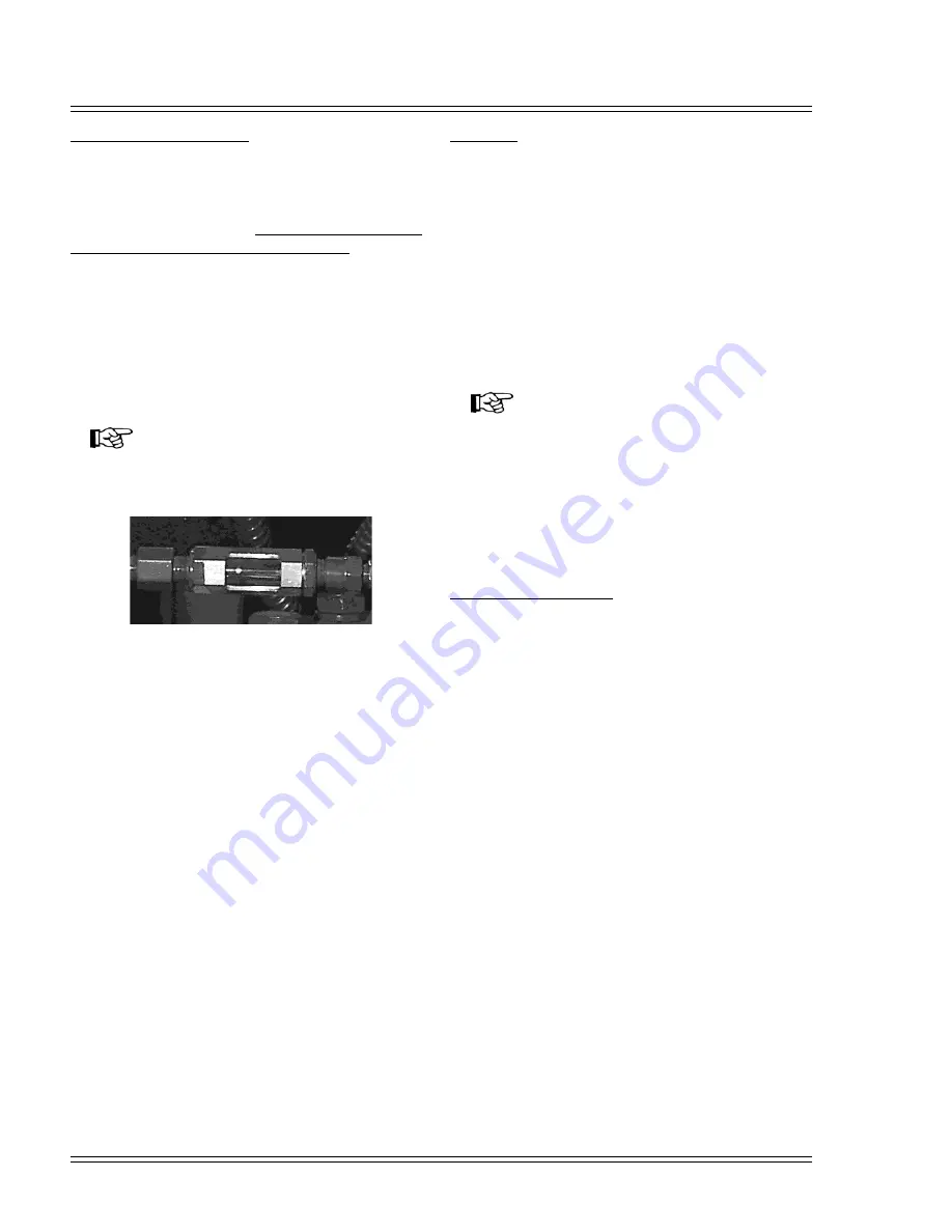
Fluid from inside the separator element is returned to the
inlet valve or airend by a scavenger tube positioned
inside the separator element, through an orifice and tube
connected to the compressor. Failure to keep the orifice
clean will result in excessive fluid carryover. Cleaning of
the orifice should be performed as follows:
• When no fluid is seen moving through the sight
glass.
• When excessive fluid carryover is detected.
• Every fluid change.
• Once per year.
NOTICE!
Do not ream the orifice or change the orifice size.
Do not install the orifice reversed.
Figure 6-1. Scavenge Line Sight Glass
Air Filter
A heavy-duty air filter is standard on all QSI models.
The heavy-duty air filter is a two stage, dry type element.
The first stage is cyclonic. That is, centrifugal airflow
spins the larger dirt particles to the outside walls of the
filter canister. In the second stage, air passes through the
filter element with an efficiency of 99.9% as tested by
SAE J7266 test code specifications. Removal and
replacement of the element is accomplished by
unscrewing the wing nut and exchanging the element.
Tighten the wing nut snugly after making certain the
element is seated correctly on its mounting base.
NOTICE!
Intake filtration equipment supplied from the
factory may not be adequate for extremely dirty
applications or some forms of dust or vapors. It
is the customer’s responsibility to provide
adequate filtration for those conditions.
Warranty will be voided if inadequate filtration
causes a failure.
Control Line Air Filter
An automatic draining control line filter is used.
Draining occurs only when the compressor is in the
unloaded condition.
Summary of Contents for QSI 1000
Page 2: ......
Page 7: ...This page intentionally left blank ...
Page 11: ...Section I General Quincy Compressor QSI 5 MODEL IDENTIFICATION ...
Page 25: ...Quincy Compressor QSI 19 THIS PAGE INTENTIONALLY LEFT BLANK ...
Page 65: ...Quincy Compressor QSI 59 THIS PAGE INTENTIONALLY LEFT BLANK ...
Page 66: ...Appendix A Dimensional Drawings 60 Quincy Compressor QSI QSI 220 245 air cooled ...
Page 67: ...Appendix A Dimensional Drawings Quincy Compressor QSI 61 QSI 220 245 water cooled ...
Page 68: ...Appendix A Dimensional Drawings 62 Quincy Compressor QSI QSI 250 300 air cooled ...
Page 69: ...Appendix A Dimensional Drawings Quincy Compressor QSI 63 QSI 250 300 water cooled ...
Page 70: ...Appendix A Dimensional Drawings 64 Quincy Compressor QSI QSI 335 370 air cooled ...
Page 71: ...Appendix A Dimensional Drawings Quincy Compressor QSI 65 QSI 335 370 water cooled ...
Page 72: ...Appendix A Dimensional Drawings 66 Quincy Compressor QSI QSI 440 500 air cooled ...
Page 73: ...Appendix A Dimensional Drawings Quincy Compressor QSI 67 QSI 440 500 water cooled ...
Page 74: ...Appendix A Dimensional Drawings 68 Quincy Compressor QSI QSI 540 600 air cooled ...
Page 75: ...Appendix A Dimensional Drawings Quincy Compressor QSI 69 QSI 540 600 water cooled ...
Page 76: ...Appendix A Dimensional Drawings 70 Quincy Compressor QSI QSI 675 750 air cooled ...
Page 77: ...Appendix A Dimensional Drawings Quincy Compressor QSI 71 QSI 675 750 water cooled ...
Page 78: ...Appendix A Dimensional Drawings 72 Quincy Compressor QSI QSI 925 1000 air cooled ...
Page 79: ...Appendix A Dimensional Drawings Quincy Compressor QSI 73 QSI 925 1000 water cooled ...
Page 80: ...Appendix A Dimensional Drawings 74 Quincy Compressor QSI QSI 1175 1250 1400 1500 air cooled ...
Page 81: ...Appendix A Dimensional Drawings Quincy Compressor QSI 75 QSI 1175 1250 1400 1500 water cooled ...
Page 99: ......


