Section VIII - Service Adjustments
Quincy Compressor-QSI
®
109
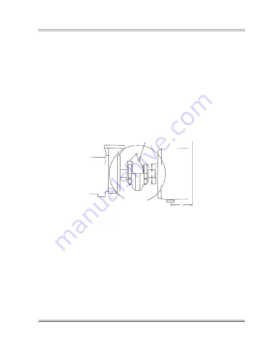
Correcting Angular Misalignment-Side View
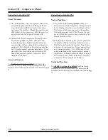
1) With the indicator point on the face of the motor
half, zero the indicator.
2) Rotate the entire assembly 180° or one-half (1/2)
turn. Note the indicator reading. This reading is re
-
ferred to as “C” in the formula and example shown.
3) Measure the distance from center to center between
the motor feet. This will be referred to as “A”.
4) Measure the O.D. of the coupling. This will be
referred to as “B”.
5) Divide measurement “A” by measurement “B”.
6) Multiply the result from step 5 by the indicator
reading “C” to determine the amount of shim to be
placed under either the front feet or the rear feet of
the motor to correct misalignment.
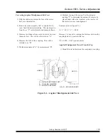
Example (refer to Figure 8-1):
A = 5”, B = 4”, C = +0.028
Because C is a positive reading, the distance between the
coupling halves is greater at the top.
5/4 x 0.028 = 0.035 required shims
Angular Misalignment Viewed From the Top
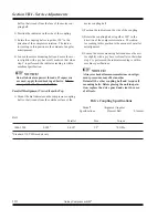
1) Mount the dial indicator on the compressor coupling
AIREND
MOTOR
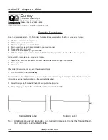
A = DISTANCE BETWEEN FEET
B = COUPLING DIAMETER
C = INDICATOR READING
C
A
B
A/B x C = REQUIRED SHIMS
Figure 8-1. Angular Misalignment-Side View
Summary of Contents for QSI Series
Page 2: ......
Page 7: ...Section I General Quincy Compressor QSI 5 MODEL IDENTIFICATION...
Page 62: ...Section IV Operating Procedures 60 Quincy Compressor QSI 1 Week Timer 2 Remaining Running Time...
Page 79: ...Section IV Operating Procedures Quincy Compressor QSI 77...

