Biasi SG Pro Series
Page 11
1. Install the supplied 3/4” elbow onto the 3/4” nipple all ready installed in the rear of the boiler.
Be certain to use a thread sealant to ensure there will be no leaks.
2. Install the Pressure Relief Valve in the 3/4” elbow being sure to use pipe sealant.
4.1 Installation of Boiler Trim Components Cont.
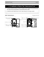
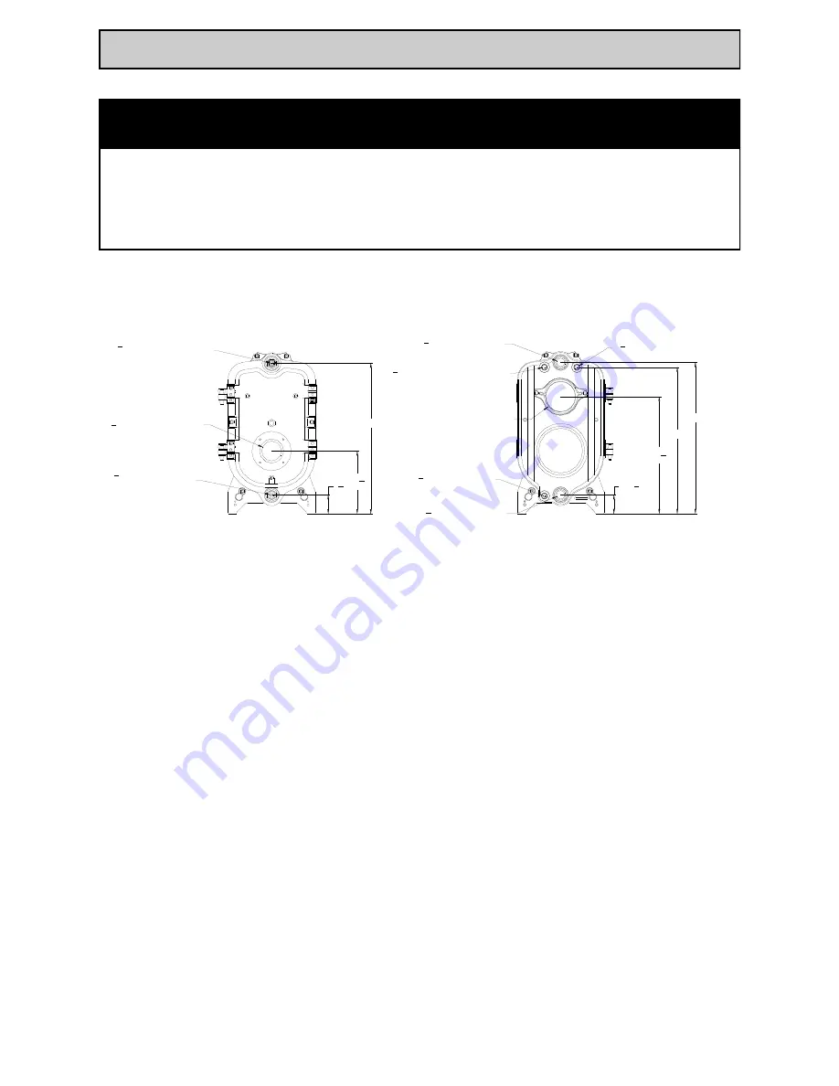
Boiler Tapping Diagram:
All dimensions are in inches:
27
2034
2x 314
Ø112 Boiler Supply Tapping
Ø112 Boiler Return Tapping
Ø34 Boiler Drain Tapping
Ø34 Hi Limit Control or PRV Tapping
Ø34 PRV or Hi Limit Control Tapping
Ø6 Exhaust Breeching
2x 26
Ø34 Control Panel Pressure
Sensor Tapping
Ø12 Control Panel Temperature
Sensor Tapping
Ø312 Burner Blast Tube Orifice
27
1114
314
27
2034
2x 314
Ø112 Boiler Supply Tapping
Ø112 Boiler Return Tapping
Ø34 Boiler Drain Tapping
Ø34 Hi Limit Control or PRV Tapping
Ø34 PRV or Hi Limit Control Tapping
Ø6 Exhaust Breeching
2x 26
Ø34 Control Panel Pressure
Sensor Tapping
Ø12 Control Panel Temperature
Sensor Tapping
Ø312 Burner Blast Tube Orifice
27
1114
314
Summary of Contents for SG-3
Page 2: ...Page 2 Biasi SG Pro Series...
Page 33: ...Biasi SG Pro Series Page 33 Notes...
Page 34: ...Page 34 Biasi SG Pro Series Notes...


