Section VI - Servicing
Belt Drive Installation Procedure
) Inspect sheave grooves for nicks.
2) Thoroughly inspect the tapered bore
of the sheave and the tapered surface
of the bushing. Any paint, dirt, metal
chips, fluid or grease MUST be
removed.
Caution!
DO NOT USE LUBRICANTS. Use of
lubricants can cause product breakage
during installation.
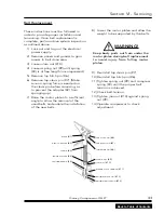
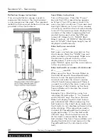
3) Position bushing and sheave
assemblies and rough align with a
metal straight edge. Mount sheaves
as close to the compressor and/or
motor housing as practical to avoid
excessive bearing and shaft loads.
With key on shaft, slide loosely
assembled unit onto shaft so that
cap screw heads are on the outside.
Locate unit in the desired position
on the shaft. When installing large
or heavy parts in the conventional
position it may be easier to mount
the key and bushing on the shaft
first, then place the product on
the bushing aligning the holes and
installing cap screws.
Caution!
When mounting on a vertical shaft,
insure that the sheave and bushing do
not drop during installation.
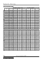
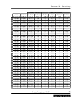
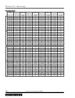
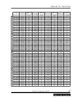
4) Tighten cap screws alternately
and evenly to the wrench torques
specified in the bushing data table on
page 5. Note: When tightened there
will be a /8” to /4” gap between
the bushing flange and the hub.
Should this gap close, then either
the shaft is undersized or the wrong
bushing shaft size is indicated.
Caution!
EXCESSIVE SCREW TORQUE MAY
CAUSE DAMAGE TO EITHER BUSHING
AND/OR PRODUCT!
5) Tighten the set screw over the key
and torque to the value listed in the
bushing data table on page 5.
6) Some conditions may exist where
step 5 will have to be completed
before step 4 as the set screw will not
be accessible once the sheave is in
place.
7) After all screws have been torqued
to their proper values, re-check the
alignment. The laser alignment
tool is highly recommended for
aligning sheaves. If the alignment
is out more than two marks on the
laser alignment tool, redo alignment
starting over at step 3.
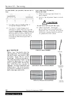
notiCe!
Misalignment of the sheaves will reduce
belt and sheave life by increasing
wear and increase the probability of
belt turn over by decreasing stability.
Misalignment comes in three varieties:
Horizontal angular, vertical angular
and parallel. Sheave alignment should
be within .078. This is the total of all
parallel and angular misalignment.
Check sheave misalignment in at least
three places after rotating one of
the sheaves 120 degrees each time,
to locate the position of maximum
misalignment.
40
Quincy Compressor-QGB
™
Back to Table of Contents

