background image

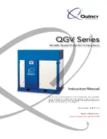
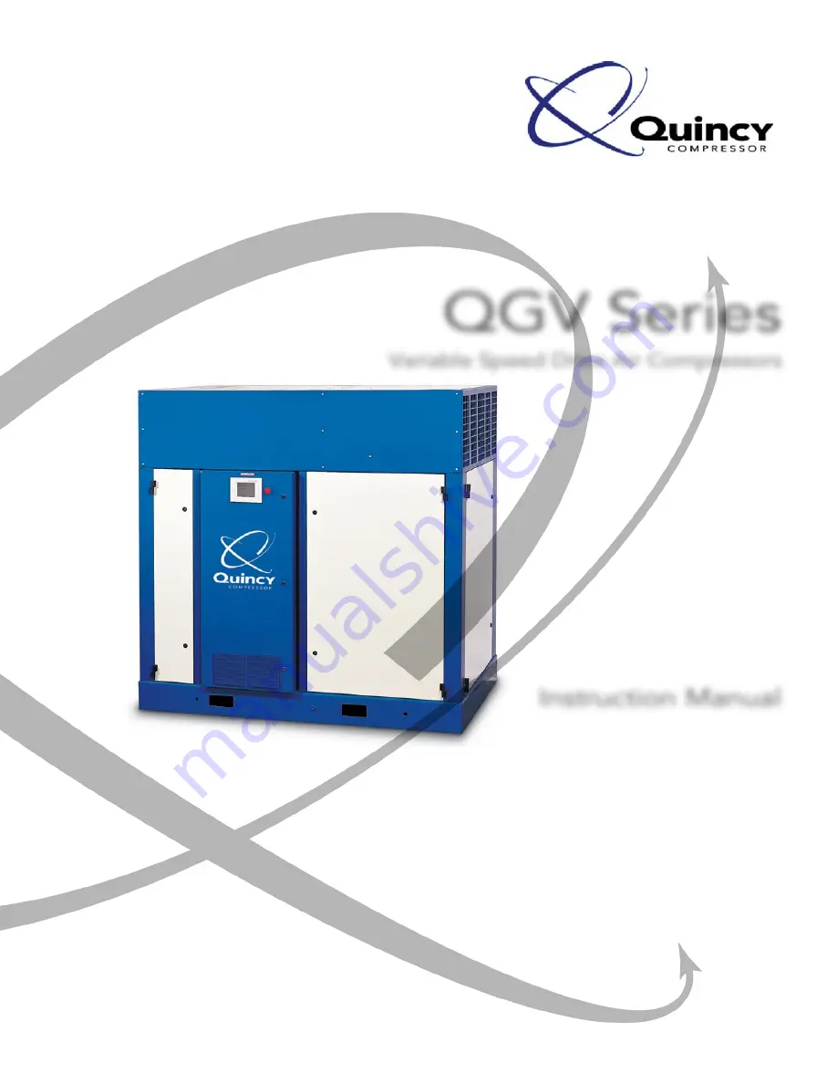
QGV Series

Variable Speed Drive Air Compressors

Instruction Manual

This  manual  contains  important  safety  information  and  should  be 

made  available  to  all  personnel  who  operate  and/or  maintain  this 

product. Carefully read this manual before attempting to operate or 

perform maintenance on this equipment.

Manual No. 65077-1A

March 2006 Edition

Latest Update: November 2008

Summary of Contents for QGV-100

Page 1: ...tains important safety information and should be made available to all personnel who operate and or maintain this product Carefully read this manual before attempting to operate or perform maintenance on this equipment Manual No 65077 1A March 2006 Edition Latest Update November 2008 ...

Page 2: ......

Page 3: ...tion III Installation Receiving 12 Moving the Unit to the Installation Site 12 Location 13 Piping Connections 14 Piping Fit up 14 Relief Valves 14 Electrical 15 Pneumatic Circuit Breakers or Velocity Fuses 15 Guards 15 Manual Vent and Shutoff Valve 15 Water and Sewer Facilities at the Installation Site water cooled models 16 Compressor Rotation 17 Fan Rotation air cooled only 17 Section IV Operati...

Page 4: ...Installation 39 Replacing Sensors or Transducers 40 Control Panel Fault or Service Messages 40 Replacing the Control Panel 41 Shaft Seal 42 Section VI Compressor Fluids Fluid Specifications 44 Lubrication 45 Fluid Sample Valve 45 Factors Affecting Fluid Life 46 Fluid Analysis Program General 46 Understanding the Analysis Report 48 QuinSyn Plus 50 QuinSyn XP 51 QuinSyn PG 52 QuinSyn F 53 QuinSyn Fl...

Page 5: ...To Air Demand 66 Compressor Does Not Unload When There Is No Air Demand 67 Compressor Does Not Revert To Load When Service Line Pressure Drops To Reset Pressure 67 Compressor Will Not Time out Or Shut Down When Unloaded Auto Dual Only 67 Excessive Water in Plant Air Distribution System 67 Pressure Relief Valve Exhausting 67 Appendix A Dimensional Drawings QGV 50 air cooled 68 QGV 50 water cooled 6...

Page 6: ......

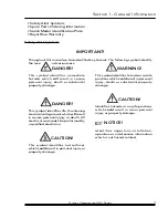
Page 7: ...n operation or maintenance information which is not hazard related IMPORTANT Throughout this manual we have identified key hazards The following symbols identify the level of hazard seriousness Danger This symbol identifies immediate hazards which will result in severe personal injury death or substantial property damage Danger This symbol identifies life threatening electrical voltage levels whic...

Page 8: ...t instructions have been included in this manual however possible product updates and changes may have occurred since this printing Quincy Compressor reserves the right to change specifications without incurring any obligation for equipment previously or subsequently sold Not responsible for typographical errors Manual Updates March 2006 Pages 3 4 Revised Warranty Added Royal Blue Warranty Page 35...

Page 9: ...rs Before any motor repairs or replacements are performed the factory must be contacted at the time of failure in order to approve any further action Drive Coupling Elements Five years 60 months from date of start up not to exceed 66 months from date of shipment including parts and labor Machine must be installed and operated in accordance with the Operator s Manual Variable Speed Drives if applic...

Page 10: ...ir replace or refund the purchase price of any product or part thereof which proves to be defective If requested by Seller such product or part thereof must be promptly returned to Seller freight collect for inspection Seller warrants factory repaired or replaced parts of its own manufacture against defects in material and workmanship under normal use and service for ninety 90 days or for the rema...

Page 11: ...______________________________________________________ ____________________________________________________________________ ____________________________________________________________________ ____________________________________________________________________ ____________________________________________________________________ ____________________________________________________________________ ...

Page 12: ...onstant mesh with a female rotor consisting of six flutes The rotors are housed in a cast iron cylinder with two parallel adjoining bores The airend has an inlet port at the power input end and a discharge port at the opposite end All parts are machined to exacting tolerances QGV model compressors use positive pressure in the reservoir to circulate the compressor fluid through the system All compr...

Page 13: ...e it is compressed then discharged into the air fluid reservoir Compressed air passes through the complete system then through a minimum pressure check valve to the service connection Capacity Control System The capacity control system on QGV compressors is a start stop control which varies air delivery based on target pressure usage As the motor begins driving the compressor rotors air is drawn i...

Page 14: ...ough the tubes Fluid leaving the cooler does not pass through a thermal mixing valve as in an air cooled unit but goes directly to the fluid filter and the compressor Fluid discharge temperature at the compressor is maintained by a water temperature regulating valve located in the discharge water line The water temperature regulating valve uses a probe to sense fluid temperature and opens and clos...

Page 15: ...e Optional panels include NEMA 4 Air cooled models utilize a second magnetic starter for protection of the fluid cooler fan motor This starter is connected to the compressor starter through an interlock which insures the fan motor is operating with the compressor motor If the fan motor starter trips out for any reason the compressor unit will shut down Danger High voltage could cause death or seri...

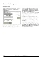
Page 16: ...e compressor A bar graph show the degree of loading of the compressor When the bars match the delivery pressure equals the pressure set point Messages indicating service items that need attention will appear on the touch screen as they are tripped The touch screen menu also provides access to various information and settings for the compressor Only trained and knowledgeable service personnel shoul...

Page 17: ...Section II Description This page intentionally left blank Quincy Compressor QGV Series 11 ...

Page 18: ...d the compressor nameplate to be sure the compressor is the model and size ordered and that optionally ordered items are included Check the reservoir and pressure relief valves to be sure they are adequate for the pressure at which you intend to operate Moving the Unit to the Installation Site Forklift slots are provided in one side and one end of the main frame Use of chains and slings should be ...

Page 19: ...red for proper compressor operation Clean air is essential for your Quincy QGV compressor Always select a source providing the cleanest air possible When an outside air source is used keep all piping as short and direct as possible Use vibration isolators and support all piping correctly Piping size should be at least as large as the inlet valve opening and increased several sizes for extremely lo...

Page 20: ...nnection on the compressor unit Relief Valves Pressure relief valves are sized to protect the system Never change the pressure setting or tamper with the valve Only the relief valve manufacturer or an approved representative is qualified to make such a change Danger Relief valves are installed to protect system integrity in accordance with ANSI ASME B19 safety standards Failure to provide properly...

Page 21: ...ses The Occupational Safety and Health Act Section 1926 303 Paragraph 7 published in Code of Federal Regulations 29 CFR 1920 1 revised 07 01 1982 states all hoses exceeding 1 2 inside diameter shall have a safety device at the source of supply or branch line to reduce pressure in case of a hose failure These pneumatic safety devices are designed to prevent hoses from whipping which could result in...

Page 22: ...sts Notice Failure to develop a water treatment p l a n m a y r e s u l t i n i n c r e a s e d maintenance and operating expense reduced equipment life and emergency shutdown Make sure the water supply is connected and open Piping supplied by the user should be at least equal to the connections provided on the compressor Sewer facilities should be readily accessible to the installation site and m...

Page 23: ...y reason follow the wiring diagram supplied with the drive motor when reconnecting the motor to the drive to ensure proper rotation Warning Operating the compressor with incorrect rotation will result in extreme damagetothecompressorandwarranty coverage will be voided Fan Rotation air cooled only Check the fan rotation prior to start up Fan airflow should be outward that is pushing the air through...

Page 24: ...Before placing the compressor into operation do the following Remove all loose items and tools from around the compressor Check fluid level in the air fluid reservoir See Compressor Fluid Section Check the fan and fan mounting for tightness Manually rotate the compressor through enough revolutions to be certain there are no mechanical interferences Check all pressure connections for tightness Chec...

Page 25: ...evel of 7 Touching the PSI Set button will bring up the password login screen Enter an appropriate password then touch Return to return to the start up screen Notice When setting up your own passwords note that the PSI Set button requires a password level greater than 1 Read Password Setup on page 26 to learn more about setting passwords and password levels Figure 4 2 Password Login Screen Once a ...

Page 26: ...nformational screen is accessed from the Start up Screen figure 4 1 and is not a password protected screen This screen shows the current operating conditions on the motor including supplied voltage s current draw computed torque and resultant horsepower The Max CFM and Min CFM are taken from the model data sheets and show the rated delivery at 110 psig Notice Other pressure settings will alter the...

Page 27: ...n Service personnel should touch the Login button to access the Password Login screen figure 4 2 and enter a password with an acceptable password level Logging in enables service personnel to move through the various menu selections without having to re enter the password Notice Once the Menu Selection screen is exited by touching Return the user will automatically be logged out Compressor Informa...

Page 28: ...ft indicates the plotted value and the scale along the bottom is the sample number The control buttons allow the graph to be viewed in varying frames from all 16 hours at one time to expanded sections that may be scrolled left or right Compress the scale increase the number of points displayed Expand the scale decrease the number of points displayed Scroll through the graph to the desired section ...

Page 29: ...an Screen is a short duration utility that allows cleaning of the touch screen surface to remove oil and fingerprints and improve clarity This utility may be used at any time without stopping the drive No input from the screen is received while the Clean Screen utility is active A timer bar indicates the available time until the program returns to the Menu Selection screen Caution Use only mild wa...

Page 30: ... the system Once the required information is entered on this screen return to the settings calculator enter the rest of the required information and press Calculate The dark grey squares require information the white squares show the results of the calculations Notice Rated CFM is the compressor s maximum output Demand is the plant usage as a of the maximum Dcy is the blow down time of the sump in...

Page 31: ...Selection screen Drive PMU Disable Touch the top button to toggle between OPS enabled and OPS disabled When OPS disabled is selected no changes can be made to the drive settings through the operator panel This prevents inadvertent setting alterations that could drastically affect the drive operations Touch Return to return to the Menu Selection screen Auto Start Setup This option enables the autom...

Page 32: ...essor Operation screen then Return again to return to the Menu Selection screen Compressor Operation Some drive settings can be altered in this menu selection however the appropriate settings are set at the factory and should not be changed without approval from the factory Touch Return to return to the Menu Selection screen Default operational settings for QGV compressors Discharge Shutdown Tempe...

Page 33: ...es can greatly affect the response to pressure changes on the compressor If changes have been made and the default settings need to be restored touch Restore Defaults Touch the PID On Off button to toggle between on and off Touch Return to return to the Compressor Operation screen then Return again to return to the Menu Selection screen Operation Limits Blow Down Timer determines how long the comp...

Page 34: ...compressor Passwords can be set using any combination of up to eight characters letters and numbers The password list is stored on the Compact Flash card Touch Retrieve Passwords to display a list of current passwords To reset the passwords follow the instructions on the Password Maintenance screen and touch Store Passwords to save Touch Return to return to the Menu Selection screen Remote Pressur...

Page 35: ...rive to be shutdown however all values in the trend buffer and local variable storage will be lost when the new program is downloaded Stopping the Compressor Normal Operation Close the service valve to the plant air distribution system Allow the pressure to build within the reservoir and the compressor to fully unload Touch the Stop button on the touch screen or remove power at the main disconnect...

Page 36: ...alve block valve between receiver and plant air system to prevent any backup of air flow into the area to be serviced NEVER depend upon a check valve to isolate the system Open the manual vent valve and wait for the pressure in the system to be completely relieved before starting service DO NOT close the manual vent valve at any time while servicing Warning Relieve compressor and system air pressu...

Page 37: ...ct a qualified serviceman Maintenance Schedule This Schedule is intended to be used as a guideline only Depending on the specific operating conditions of your QGV compressor maintenance requirements may vary The instructions on the following pages will give more details about determining when specific service should be performed Notice Reference pages 32 thru 43 for specific instructions on perfor...

Page 38: ...val Water vapor may condense in the reservoir and must be removed Water is heavier than the compressor fluid and will collect at the bottom of the reservoir The frequency with which the water must be removed is determined by the ambient air conditions During hot and humid conditions water should be drained off the bottom of the reservoir daily In cold and dry conditions water may only need to be d...

Page 39: ...e cooling water supply can impact the service life of the heat exchanger It is strongly recommended that a reputable local water treatment company be engaged prior to start up to establish the corrosion scale forming and fouling tendency of the cooling water and remedy the situation if a problem does exist Notice Failure to develop a water treatment p l a n m a y r e s u l t i n i n c r e a s e d ...

Page 40: ...tenance or Service on page 28 and Safety instructions on page 30 Slowly unscrew the plugs at the fluid fill and discharge port Attach a pipe to the drain valve open the drain valve and allow all the fluid to drain from the unit In order for all fluid to be removed fluid should be at running temperature between 140 F and 175 F Dispose of the fluid in accordance with Local State and Federal environm...

Page 41: ... off the fluid level in the compressor Never mix different types of fluid To top off the fluid level add fluid Turn the compressor off by the main switch and perform proper lockout tagout procedure Completely depressurize the compressor circuits reference Preparing for Maintenance or Service on page 28 and Safety instructions on page 30 Wait one minute and check the fluid level Unscrew the fluid f...

Page 42: ...ior of the fluid cooler aftercooler should be cleaned periodically to ensure sufficient cooling capability Dirty fins in the cooler degrade the ability for the cooler to work properly To clean the cooler fins Switch the compressor off by the main switch and perform proper lockout tagout procedure Clean the cooler fins using compressed air Fluid Tubing Flareless tubing is used in the fluid piping t...

Page 43: ...H TIGHTEN WRENCH TIGHTEN LOCKNUT 1 CHECK SEALING SURFACES INSTALL O RING INSPECT FITTING FOR DAMAGE USE O RING INSTALLATION TOOL TO INSTALL O RING APPLY SMALL AMOUNT OF LUBRICANT TO O RING LOCKNUT BACKUP WASHER O RING INSPECTSEALING SURFACES FOR DAMAGE INSTALL O RING THREAD FITTING INTO PORT AND WRENCH TIGHTEN CHECKSEALINGSURFACE AND GROOVE FOR DAMAGE OR MATERIAL BUILDUP ENSURETHATO RINGISPROPERLY...

Page 44: ...e voided if inadequate filtration causes a failure Air Fluid Separator Element The separator element is a one piece construction that coalesces the fluid mist passing through the filtering media into droplets that fall to the bottom of the separator element to be picked up by a scavenging tube and returned to the compressor Use care when handling the separator element to prevent it from being dama...

Page 45: ...nt has a gasket on each side of the flange repeat steps 3 through 7 9 If the separator element fails any of the above test return it to your Quincy Distributor for replacement 10 Make sure the compressor is bonded wired to an earth ground to dissipate static electricity Added QGV 150 200 Separator Installation 10 01 07 QGV 150 200 Separator Installation The 150 and 200 horsepower models utilize an...

Page 46: ...rtion of the printed circuit board ground yourself using a grounding wrist strap to remove any static electricity After assuring the compressor is properly grounded clip the grounding wrist strap to any exposed metal on the frame of the compressor Disconnect transducer wires at microprocessor Remove transducer from delrin bushing Replace the delrin bushing Install new Teflon bushing and transducer...

Page 47: ...s Notice Prior to touching any portion of the printed circuit board ground yourself using a grounding wrist strap to remove any static electricity After assuring the compressor is properly grounded clip the grounding wrist strap to any exposed metal on the frame of the compressor Identify individual wire location s Reference the electrical wiring diagram found in the control panel of the unit Inst...

Page 48: ...seal cavity will not scavenge Replace if necessary Remove the coupling guards and coupling halves Remove the drive coupling hub and key from the compressor shaft Remove the drive motor Remove the four bolts securing the seal adapter to the suction housing Insert two of the seal adapter retaining bolts into the seal adapter jack holes and turn clockwise pushing the seal adapter away from the suctio...

Page 49: ...o the inner diameter of the wear sleeve and immediately install on the compressor shaft using the proper wear sleeve driver Drive the wear sleeve on the shaft until the driver bottoms on the shaft shoulder Seal Installation Apply a thin coat of compressor fluid to the outer face of the wear sleeve and seal lip Slide the proper seal installation sleeve against the wear sleeve with the taper toward ...

Page 50: ...ions Fluid Specifications Lubrication Fluid Sample Valve Factors Affecting Fluid Life Fluid Analysis Program General Sampling Procedures Understanding the Analysis Report QuinSyn Plus QuinSyn XP QuinSyn PG A fluid tag is attached to each Quincy rotary screw compressor indicating the type of fluid provided in the initial fill All of the fluids listed are available from any authorized Quincy distrib...

Page 51: ...Each Quincy compressor is filled at the factory with the correct amount of one of the synthetic fluid listed in the Fluid Specifications Mineral oil can be requested and used in specific applications The use of other brands or types of fluid may reduce the design life of the compressor or cause problems with filtration or carryover Consult the Quincy Service Department before changing brands of fl...

Page 52: ...inSyn fluids Monitoring of the total acid number TAN barium level and or viscosity throughout the life of the fluid provides maximum protection to your machine while best utilizing the extended life features of QuinSyn The fluid analysis provides historical information detailing items such as hours on the fluid viscosity and total acid number TAN Should results appear unusual or suspicious a detai...

Page 53: ...drain 2 4 ounces of fluid from filter and discard in an approved manner 2 Fill sample bottle 3 Close valve After collecting sample from either of the above methods 1 Fill out information label completely Notice Be certain to provide all information as to possible hazards related to a given sample if hazards exist the information must be clearly marked on the sample bottle label 2 Attach Sample Bot...

Page 54: ...umber of the Quincy compressor that the fluid sample was taken from i HOURS ON FLUID These are the actual hours that the QuinSyn fluid has been in the unit since the last fluid change j HOURS ON MACHINE This is the total hours on the compressor hourmeter k SAMPLE DATE The date that the sample was taken from the compressor Notice Items c through k are information provided by the service person supp...

Page 55: ...n parts per million ppm Date Silver Alum Chrom Copp Iron Nickel Lead Tin Titan Vanad Bari Calc Mag Mol Sod Phos Sili Zinc Fluid Hours Ag Al Cr Cu Fe Ni Pb Sn Ti V Ba Ca Mg Mo Na P Si Zn Thank you for this opportunity to provide technical assistance to your company If you have any questions about this report please contact us at 1 800 637 8628 or fax 1 517 496 2313 means this parameter not tested A...

Page 56: ...y Better gas fluid separation Typical Properties of QuinSyn Plus ISO 46 Viscosity 100 F ASTM D445 46 0 cSt Viscosity 210 F ASTM D445 7 5 cSt Viscosity Index ASTM D2270 127 Specific Gravity 60 60 0 89 Flash Point ASTM D92 475 F Fire Point ASTM D92 540 F Pour Point 58 F Applications QuinSyn Plus is suited for use in rotary screw air compressors operating in harsh service conditions where the fluid i...

Page 57: ...M D445 9 8 cSt Viscosity Index ASTM D2270 131 Specific Gravity 60 60 0 95 Flash Point ASTM D92 570 F Fire Point ASTM D92 645 F Applications QuinSyn XP is designed for applications where the fluid is exposed to elevated temperatures for extended periods of time Fluid thermostat temperature settings can be elevated to assist in reducing water content in the fluid in high humidity applications Consul...

Page 58: ...of this fluid should be done in accordance with Local State and Federal regulations Separation of this fluid from condensate will require those separators designed to handle fluid emulsions The QIOW fluid water separator is suitable for separation of fluid emulsions such as QuinSyn PG Please contact Quincy s Service Department for more details Fluid Analysis Program The fluid sampling for QuinSyn ...

Page 59: ...cosity Index ASTM D2270 139 Flash Point ASTM D92 495 F Fire Point ASTM D92 560 F Pour Point 76 F Specific Gravity 60 60 0 83 Color Water white White Changes to color will occur during operation QuinSyn Flush QuinSyn Flush is a specially formulated synthetic fluid capable of dissolving varnish and solubilizing sludge from lubricating systems while they are operating QuinSyn Flush contains oxidation...

Page 60: ...hange the separator element and all filters Refill with a fresh charge of the QuinSyn fluid selected for your machine Send a fluid sample to Quincy Compressor Fluid Analysis at 200 hours Polyalklene glycols PAG or Silicone Drain compressor thoroughly as in A Fill machine with QuinSyn Flush and run for 500 hours Send fluid sample to Quincy Compressor Fluid Analysis to determine if further flushes a...

Page 61: ...as in A Fill with QuinSyn Flush and run for 300 hours Send fluid sample to Quincy Compressor Fluid Analysis to determine if further flushes are needed Run the flush for an additional 300 hours Drain thoroughly as in A and inspect the compressor If clean flush with another half charge of QuinSyn Flush and run for 30 minutes Drain completely Change filters and separator element and all filters and f...

Page 62: ...using mineral oils or PAO fluids flush the compressor with QuinSyn Flush following the procedures outlined on page 55 Converting to QuinSyn XP Normal Machines To convert a clean machine presently using any QuinSyn fluid to QuinSyn XP No flush required Drain compressor thoroughly while hot including all the low areas fluid lines and the fluid cooler Shut down and lockout the machine Change the sepa...

Page 63: ...nce with all local state and federal disposal regulations Refill with a fresh charge of QuinSyn Flush and change the fluid filter Run compressor for 300 hours Take a fluid sample and send to Quincy Compressor Fluid Analysis to determine if further flushing is needed Proceed as instructed by the fluid analysis report Notice More than one flush may be required to remove varnish buildup and reduce th...

Page 64: ...nSyn XP 0 40 50 100 QuinSyn PG 0 40 50 100 Phosphorus PPM Plasma Emission QuinSyn Plus 0 5 20 20 QuinSyn XP 50 5 20 0 QuinSyn PG 0 5 20 20 Zinc PPM Plasma Emission All 0 100 200 200 Wear Metals Silver PPM Plasma Emission All 0 5 10 10 Aluminum PPM Plasma Emission All 0 5 10 10 Chromium PPM Plasma Emission All 0 5 10 10 Copper PPM Plasma Emission All 0 5 10 10 Iron PPM Plasma Emission All 0 5 10 10...

Page 65: ...PM Plasma Emission All 0 100 200 200 Wear Metals Silver PPM Plasma Emission All 0 5 10 10 Aluminum PPM Plasma Emission All 0 5 10 10 Chromium PPM Plasma Emission All 0 5 10 10 Copper PPM Plasma Emission All 0 5 10 10 Iron PPM Plasma Emission All 0 5 10 10 Nickel PPM Plasma Emission All 0 5 10 10 Lead PPM Plasma Emission All 0 5 10 10 Tin PPM Plasma Emission All 0 5 10 10 Titanium PPM Plasma Emissi...

Page 66: ...use Correct the situation in accordance with the instruction in the High Discharge Air Temperature section of this troubleshooting guide Restart the compressor Ask the power company to make a voltage check at your entrance meter then compare that reading to a reading taken at the motor terminals Use these two readings as a basis for locating the source of low voltage Check power supply to the unit...

Page 67: ...on in the High Discharge Air Temperature section of this troubleshooting guide Restart the compressor Check power supply and transformer fuses Contact a qualified service technician for repairs Check all wiring terminals for contact and tightness Lower full load pressure setting at control panel Check voltage and amperage while operating at full load pressure Check all connections for tightness Ch...

Page 68: ...r replace with new element Check service lines for leaks with soap suds Repair as necessary Check for build up or gumming of shaft Check fluid filter for plugging Reevaluate air demand Install additional compressors as needed Check service lines for leaks with soap suds Repair as necessary Correct in accordance with the instructions in Inlet valve not opening or closing in relation to air demand s...

Page 69: ...or adjust if necessary Check location of cooler and assure no restriction to free circulation of cooling air Check cooler fin and clean as necessary Add fluid to recommended level Check fluid system for leaks Replace all panels ensure all sealing surfaces and materials are satisfactory Clean cooler find and correct cause of contamination Replace fluid filter element s Maximum ambient for proper op...

Page 70: ...ements replace them If air filter is inadequate for the environment relocate the intake air to a clean source Replace fluid filter element Correct in accordance with the instruction in Fluid Breakdown section of the troubleshooting guide Use genuine Quincy replacement elements only Operate compressor at recommended reservoir pressure and discharge air temperature Do not mix different grades or typ...

Page 71: ... troubleshooting guide Check and clean system of all dirt corrosion and varnish Drain water as needed to reduce water content in fluid below 200 PPM Check operation of thermostatic valve or water regulating valve If condition continues consult Quincy service department Fluid Discharge Out Blowdown Valve Too high fluid level in reservoir Air fluid reservoir blows down too fast Inlet valve not closi...

Page 72: ...luid level to recommended fluid level by draining the reservoir Use fluid level gauge as a guide Clean scavenger line orifice and tube Correct in accordance with the instructions in High discharge air temperature section of this troubleshooting guide Reservoir pressure should not fall below 50 PSIG when running loaded Check system CFM requirement and minimum pressure check valve Change air fluid s...

Page 73: ...ture separator trap Installation Application Faulty cooler leaks Pressure Relief Valve Exhausting Plugged separator Faulty receiver pressure gauge Faulty pressure relief valve Repair or replace as necessary Check lines before MPC valve Check and tighten wiring terminals Check and repair air inlet valve Check plant air distribution system for leaks Replace as necessary Clean or replace as required ...

Page 74: ...Appendix A Dimensional Drawings QGV 50 air cooled 68 Quincy Compressor QGV Series ...

Page 75: ...Appendix A Dimensional Drawings QGV 50 water cooled Quincy Compressor QGV Series 69 ...

Page 76: ...Appendix A Dimensional Drawings QGV 75 100 air cooled 70 Quincy Compressor QGV Series ...

Page 77: ...Appendix A Dimensional Drawings QGV 75 100 water cooled Quincy Compressor QGV Series 71 ...

Page 78: ...Appendix A Dimensional Drawings QGV 150 200 air cooled 72 Quincy Compressor QGV Series ...

Page 79: ...Appendix A Dimensional Drawings QGV 150 200 water cooled Quincy Compressor QGV Series 73 ...

Page 80: ...390 2410 Aftercooler BTU min 340 340 338 342 Aftercooler Approach standard conditions F 5 7 Maximum Allowable Static Backpressure in H2 O 0 125 Fan Motor HP 2 Fan Motor rpm 1743 Fan Flow cfm 3390 Water cooled Cooling Water In Out Size In npt 1 Recommended Inlet Water Pressure psig 45 100 Vent Fan Motor HP 1 9 Aftercooler Approach to Cooling Water Temperature F 13 18 Water Flow with Aftercooler at ...

Page 81: ...min 530 528 525 528 Aftercooler Approach standard conditions F 5 7 Maximum Allowable Static Backpressure in H2 O 0 125 Fan Motor HP 5 Fan Motor rpm 1743 Fan Flow cfm 6290 Water cooled Cooling Water In Out Size In npt 1 Recommended Inlet Water Pressure psig 45 100 Vent Fan Motor HP 1 9 Aftercooler Approach to Cooling Water Temperature F 13 18 Water Flow with Aftercooler at 70 F gpm 10 90 F gpm 18 C...

Page 82: ...nown Aftercooler Approach standard conditions F 5 7 Maximum Allowable Static Backpressure in H2 O 0 125 Fan Motor HP 5 Fan Motor rpm 1743 Fan Flow cfm 5200 Water cooled Cooling Water In Out Size In npt 1 Recommended Inlet Water Pressure psig 45 100 Vent Fan Motor HP 1 9 Aftercooler Approach to Cooling Water Temperature F 13 18 Water Flow with Aftercooler at 70 F gpm 10 10 4 13 2 unknown 90 F gpm 1...

Page 83: ...er BTU min 658 Aftercooler Approach standard conditions F 5 7 Maximum Allowable Static Backpressure in H2 O 0 125 Fan Motor HP 5 Fan Motor rpm 1180 Fan Flow cfm 13500 Water cooled Cooling Water In Out Size In npt 1 25 Recommended Inlet Water Pressure psig 45 100 Vent Fan Motor HP 1 9 Aftercooler Approach to Cooling Water Temperature F 13 18 Water Flow with Aftercooler at 70 F gpm 13 1 90 F gpm 20 ...

Page 84: ...0 Aftercooler Approach standard conditions F 5 7 Maximum Allowable Static Backpressure in H2 O 0 125 Fan Motor HP 5 Fan Motor rpm 1159 Fan Flow cfm 16200 Water cooled Cooling Water In Out Size In npt 1 Recommended Inlet Water Pressure psig 45 100 Vent Fan Motor HP 1 9 Aftercooler Approach to Cooling Water Temperature F 13 18 Water Flow with Aftercooler at 70 F gpm 10 10 4 13 2 unknown 90 F gpm 17 ...

Page 85: ...________ Start up Date____________________ Maint Record Sheet Maintenance Item A ir F ilter F luid F ilter A ir F luid S eparator F luid S ample F luid T opped O ff F luid C hange F luid C ooler Date Hourmeter Reading Service Performed replaced cleaned etc Quincy Compressor QGV Series 79 ...

Page 86: ...d to seller freight prepaid for inspection Seller warrants repaired or replaced parts of its own manufacture against defects in materials and workmanship under normal use and service for ninety 90 days or for the remainder of the warranty on the product being repaired This warranty shall not apply and Seller shall not be responsible or liable for a Consequential collateral or special losses or dam...

Page 87: ...isk and storage charges may be applied at the discretion of Seller Accounts past due shall bare interest at the highest rate lawful to contract for but if there is no limit set by law such interest shall be eighteen percent 18 Buyer shall pay all cost and expenses including reasonable attorney s fees incurred in collecting the same and no claim except claims within Seller s warranty of material or...

Page 88: ..._____________________________________________________ ____________________________________________________________________ ____________________________________________________________________ ____________________________________________________________________ ____________________________________________________________________ ____________________________________________________________________ _...

Page 89: ......

Page 90: ... 2006 Quincy Compressor All Rights Reserved Litho in U S A Quincy Compressor Products 217 222 7700 E mail info quincycompressor com Website www quincycompressor com ...

Reviews: