background image


QMB/T

®

 Control Operations 

 
This manual describes the microprocessor control for the QMB/T series of Air Compressors. 
 
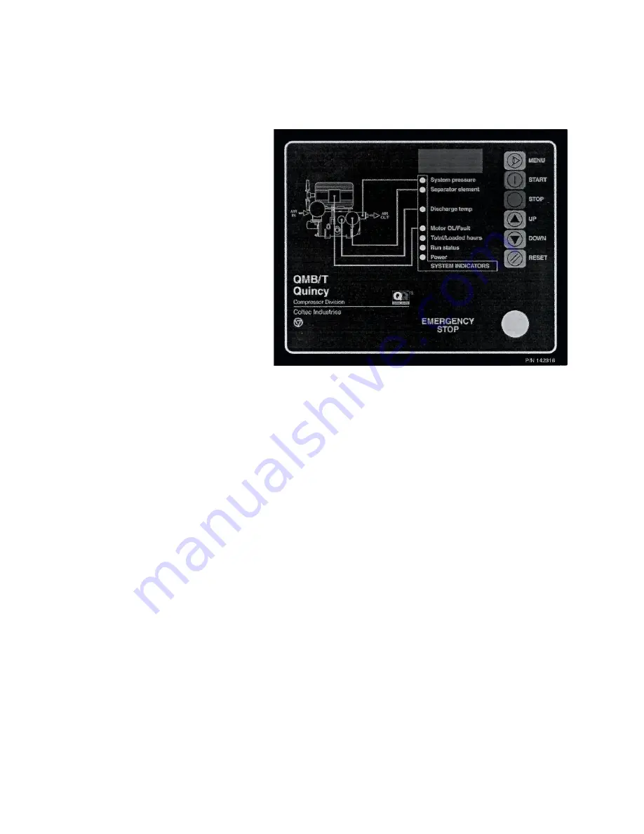
The decal at the right shows the control 
layout for the electronic control panel. 
 
The primary controls are on the right 
hand side of the panel, with the selected 
item being displayed on the LED digits 
in the top window. 
 
The LED lamps in a vertical column, 
show the selected display parameter 
and/or any alarm conditions. 
 
On applying system power the LED 
status lights will blink and the numeric 
display will show the version number of 
the software code installed.  The system 
will be ready to run with the 'POWER' 
lamp on (showing that the control board  
has power) and the 'SYSTEM PRESSURE' LED will be lit showing the pressure on the numeric display. 
 
NOTE: A flashing '----' on the digit display, accompanied with an LED on the left, signifies a faulty 
sensor, either the pressure transducer or the temperature probe. 
 

FAST 

blinking LED indicates that the labeled function has been tripped; an over-pressure condition or 

motor overload or High Air Temperature (HAT) trip. 
 

SLOW 

blinking LED indicates that the Separator Differential Pressure (D.P.) switch has been tripped.  

STEADY 

LED, along with a message blinking on the display, indicates a service time-out.  The 

controller is programmed with recommended service intervals on the fluid filter and the air filter.  These 
filters should be checked and serviced when convenient. 


Summary of Contents for QMB Series

Page 1: ...tion Quincy QMB T Series Electronic Control Instruction Manual This manual contains important safety information and should be made available to all personnel who operate and or maintain this product Carefully read this manual before attempting to operate or perform maintenance on this compressor ...

Page 2: ......

Page 3: ...n with the POWER lamp on showing that the control board has power and the SYSTEM PRESSURE LED will be lit showing the pressure on the numeric display NOTE A flashing on the digit display accompanied with an LED on the left signifies a faulty sensor either the pressure transducer or the temperature probe A FAST blinking LED indicates that the labeled function has been tripped an over pressure condi...

Page 4: ...f no major faults are present open pressure sensor temperature sensor high temperature condition or overload NOTE The RUN STATUS LED will be ON to show that a start cycle is in progress The compressor will not start if the line pressure is above the load point the compressor will start when the line pressure drops below the load point If the compressor is waiting to start the Run Status LED will f...

Page 5: ...RATING ADJUSTMENTS LED 1 Use the MENU key to select the UNLOAD pressure as indicated by a U at the left most digit Use the UP or DOWN keys to adjust NOTE Value is saved when display is no longer blinking Use the MENU key to then select the LOAD pressure as indicated by an L at the left most digit Use the UP or DOWN keys to adjust LED 2 This allows the adjustment of the Wye Delta Y D time on the co...

Page 6: ...e hours setup The display will show the hours remaining alternating with FLu On servicing the fluid filter or taking a sample this counter should be re set to the desired service interval The LED s described above will blink when the service intervals reach 00 in the main running display As before the setting is saved when the display reading is steady MENU 03 DISPLAY UNITS AND MODEL TYPE LED 1 Se...

Page 7: ...h if the main contactor fails to close properly or fails to open in a controlled shutdown 3 OVERLOAD This LED will light if the motor overload has tripped LED MESSAGE INDICATORS 1 Excessive pressure Error Top LED flashes fast 2 Separator Element clogged Second LED flashes slowly 3 Air Filter timer expired The message AIRF flashes on the display 4 Excessive Temperature Third LED flashes slowly 5 Te...

Page 8: ...he Teflon bushing is recommended any time a transducer is replaced Install new Teflon bushing and transducer Connect transducer wires to microprocessor and reinstall wire channel cover Replacing electronic control NOTE Prior to touching any portion of the printed circuit board you will need to ground yourself to remove any static electricity using a grounding wrist strap After assuring the compres...

Page 9: ...7 WIRING DIAGRAM ACROSS THE LINE STARTING ...

Page 10: ...8 WIRING DIAGRAM WYE DELTASTARTING ...

Page 11: ......

Page 12: ...ll help keep you in business Call for Authorized Quincy Service Quincy Compressor T r u e B l u e R e l i a b i l i t y SM Rotary Vacuum Systems 251 937 5900 Reciprocating Systems 217 222 7700 Nearest Distributor 888 424 7729 E mail trueblue quincycompressor com Discover www quincycompressor com 2003 Quincy Compressor an EnPro Industries company EnPro Industries company EnPro Industries All Rights...

Reviews: