5
INSTALLATION INSTRUCTIONS
LOCATING THE DRYER
FLOOR
The floor must be even and of industrial type; the total
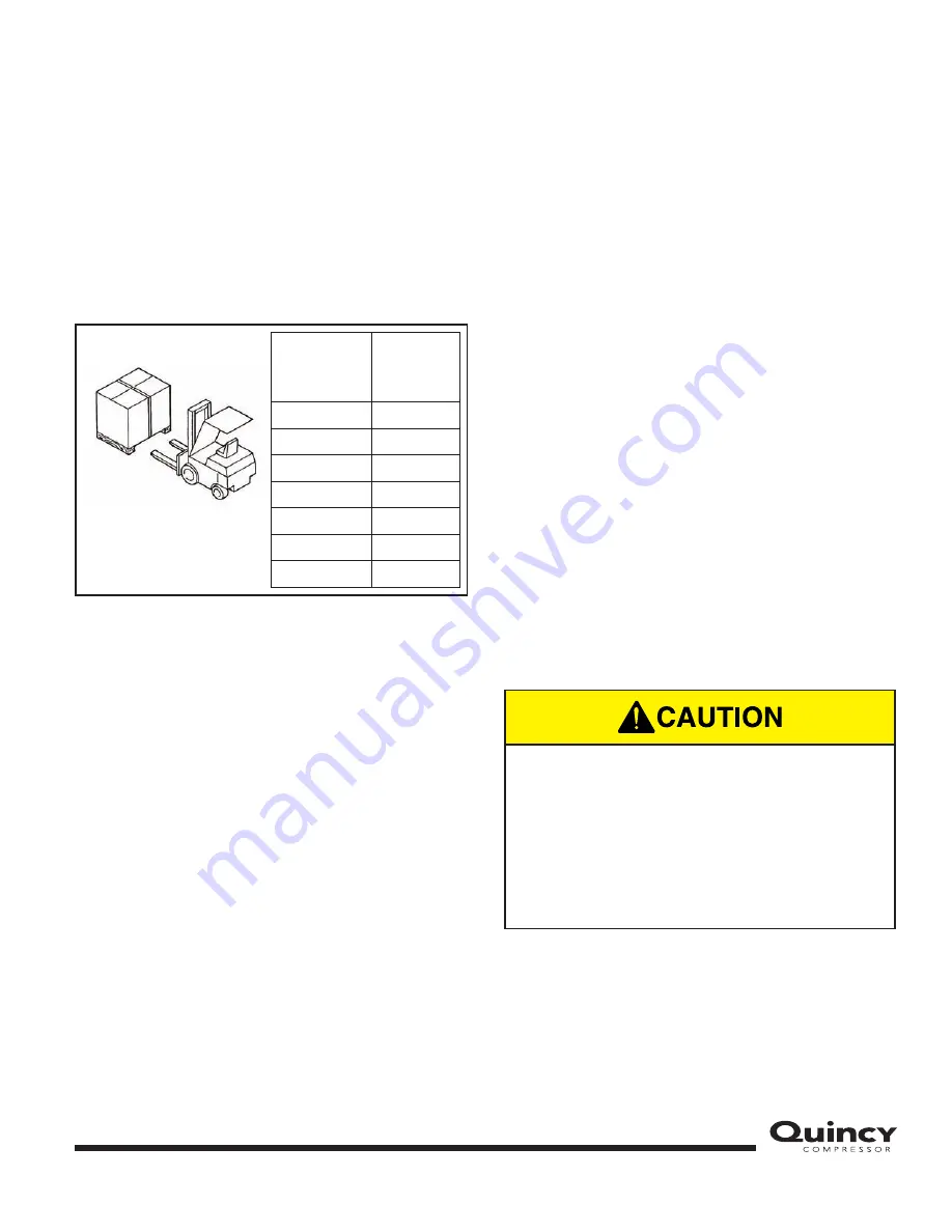
weight of the machine is shown in Figure 4.
Consider the total weight of the machine when positioning it.
Consider the total weight of the machine when positioning it.
FIGURE 4 — MODEL WEIGHT
VENTILATION
The choice of an appropriate room will prolong the life of
your dryer. The room must be spacious, dry, well-
ventilated and free from dust.
DESIGN CONDITIONS
Min. room temperature:
+ 40 °F (+ 4.5 °C)
Max. room temperature:
+ 115 °F (+ 46 °C)
Min. temperature of incoming air:
+ 40 °F (+ 4.5 °C)
Max. temperature of incoming air:
+ 131 °F (+ 55 °C)
Max. working pressure:
203 psi (14 bar)
TRANSPORT AND HANDLING
The machine must be transported as shown in Figure 4.
POSITIONING
After unpacking the equipment, preparing the dryer’s
room, and putting the machine into position, check the
following items:
1.
Ensure that there is sufficient space around the
machine to allow maintenance (see Fig. 5).
2.
Ensure that the operator can see the whole machine
from the control panel and can check for the
presence of unauthorized persons in the machine’s
vicinity.
ELECTRICAL CONNECTION
1.
Check that the supply voltage is the same as the
value indicated on the machine’s identification plate.
2.
Check the condition of the line leads and ensure that
there is an efficient earth ground lead.
3.
Dryer must be wired to the power supply through a
fused disconnect switch or circuit breaker in
accordance with national and local electrical codes
to protect against overcurrents, with ground-fault
circuit interrupter protection, if required by local
codes (see Figure 5).
NOTE:
There is a copy of the wiring diagram inside the
electric panel.
Model
Gross
Weight
lb. (kg.)
QPNC 75
112.4 (51)
QPNC 100
134.5 (61)
QPNC 125
149.9 (68)
QPNC 150
198.4 (90)
QPNC 175
198.4 (90)
QPNC 200
198.4 (90)
QPNC 250
198.4 (90)
Only professionally skilled personnel may
have access to the electrical panel. Switch
off the power supply before opening the
door to the electrical panel. Compliance
with national and local codes concerning
electrical plants is fundamental for operator
safety and for the protection of the
machine.
Summary of Contents for QPNC 100
Page 16: ...14 QPNC 75 External Parts List...
Page 18: ...16 QPNC 75 Internal Parts List...
Page 20: ...18 QPNC 100 125 External Parts List...
Page 22: ...20 QPNC 100 125 Internal Parts List...
Page 24: ...22 QPNC 150 200 250 External Parts List...
Page 26: ...24 QPNC 150 200 250 Internal Parts List...
Page 28: ...26 QPNC 75 Dimensional Drawing...
Page 29: ...27 QPNC 100 125 Dimensional Drawing...
Page 30: ...28 QPNC 150 to 250 Dimensional Drawing...
Page 31: ...29 QPNC 75 115V Wiring Diagram...
Page 32: ...30 QPNC 75 230V Wiring Diagram...
Page 33: ...31 QPNC 100 125 115V Wiring Diagram...
Page 34: ...32 QPNC 100 125 230V Wiring Diagram...
Page 35: ...33 QPNC 150 175 200 250 Wiring Diagram...
Page 36: ......
Page 37: ......


