MedTrack CR60 Rehabilitation Treadmill Service Manual
Theory of Operation 2-3
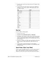
Output Displays
The controller assembly uses LED displays mounted on the controller
PCBA. These displays show pertinent treadmill information including
target speed and grade and accumulated exercise information.
Additional Functions
The controller assembly also:
•
performs an electronic self-test when the treadmill is turned on
•
provides a special mode for manufacturing and service testing
•
includes circuitry for the magnetic access switch.
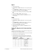
Controller to Treadmill Interface
The controller communicates with the treadmill drive board through a
standard RS422 interface. The controller sends commands to the
treadmill drive board and receives acknowledge and status statements
from the treadmill drive board. The controller uses 12 VDC power from
the treadmill drive board as the power source for all circuitry and for the
LED displays.
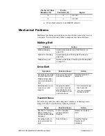
Headframe Assembly
The headframe assembly consists of the following components:
•
Input power module
•
Drive board assembly
•
Transformer assembly
•
Drive motor assembly
•
Grade motor assembly
•
Grade system consisting of a pinion shaft, rack gears, feedback
potentiometer, and limit switches.
Input Power Module
The input power module receives line power from the power outlet. The
MedTrack CR60 Rehabilitation Treadmill is available in two voltage
ranges. Low voltage units have a nominal range of 100-120 VAC. The
high voltage units have a range of 200-240 VAC.
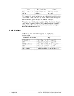
Drive Board
The treadmill drive board uses line power to develop 300 VDC that is
then used to create three-phase power for the drive motor assembly. The
frequency of the three-phase signal sent to the drive motor determines the
drive motor rotational speed. The motor current draw is a function of the
torque load placed on the motor through the deck assembly by the user.


