background image

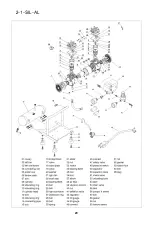
2-1-SIL

.. 

� 

� 

---------

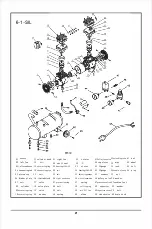
part  list 

01 

,.....,. 

12 

cylinder  heed 

23 

nhe  plate 

,. 

bolt 

.. 

Clll)IICitorocne:r 

58 

"'""'' 

02 

left  fan 

13 

bolt 

24 

"'" 

bolt 

.. 

UDloedina ttibe 

Deflaticmalff 

03 

l.t'toramoas, 

••

pro  tect  COTI'1" 

,. 

..... 

.. 

apriJII' 

"  """"°"" 

58 

.,_ 

"' 

"""""ingrod 

15 

bolt 

,. 

bolt 

1tatar 

.. 

B:meult  pipe 

.. 

...., 

06 

pbt011  cup 

16 

fimd  block 

27 

rilht  fan 

mrt 

.. 

�  nitch 

., 

Adjwit  hol.dlr 

.. 

!indar  plat• 

17 

obturatinp'in, 

28 

shaft  seal 

,. 

,..,...,, 

., 

SafetJ  ,-a1,. • 

61 

bolt 

07 

bolt 

18 

CODDectll!IPipe 

29 

besrioa80()6-2Z 

.. 

bNrin,6209-2Z 

51 

,11,.,. 

.. 

-

08 

CJlindm:-

19 

., 

...

., 

bolt 

41 

dbratioacolma. 

02 

.,. 

., 

,11,.,. 

09 

obtuntill2Ii111 

20 

bolt 

SI 

bolt 

.,  "''"' 

.. 

bolt 

.. 

............ 

10 

air  filtl!E' 

21 

li.mitedblock 

,. 

riaht  cankcale 

.. 

Hlf  tappfna: 

.. 

C\llhim  foot 

65 

dn!n-

l! 

obturatiDP'illl' 

22 

,al,o 

,. 

protectionr:lna: 

.. 

capacitor 

55 

handle  llffff 

19 

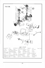
Summary of Contents for 10-2-SIL

Page 1: ...COMPRESSOR ...

Page 2: ......

Page 3: ...18 19 17 17 12 OPERATING THE AIR COMPRESSOR Preparing for Start up Starting the Compressor Checking the Safety Valve Running the Air Compressor Draining the Tank Storage CARE CLEANING TROUBLESHOOTING SERVICE PARTS following symbols ...

Page 4: ...dust ...

Page 5: ...irect a jet of compressed air toward people or animals Protect your lungs Wear a face or dust mask if the operation is dusty Do not use this air compressor to spray chemicals Your lungs can be damaged by inhaling toxic fumes A respirator may be necessary in dusty environments or when spraying paint This compressor is equipped with a thermal overload protector which will shut off the motor if it be...

Page 6: ...ft ...

Page 7: ...1 68 ...

Page 8: ... Pressure switch Motor Safety valve I Capacitor Regulator Pressure gauge Tank Filter Ball valve 2 1 SIL 2 1 SIL AL 6 1 SIL 10 2 SIL 3 20 CFM 3 20 CFM 3 20 CFM 5 60 CFM 2 20 CFM 2 20 CFM 2 20 CFM 4 40 CFM 125PSI 125PSI 115PSI 125PSI Electric Electric Electric Electric 1 0hp 1 0hp 1 0hp 2 0hp 1680 RPM 1680 RPM 1680 RPM 1680 RPM 120V 60HZ 120V 60HZ 120V 60HZ 120V 60HZ Oil Free Oil Free Oil Free Oil F...

Page 9: ...erate the Air Compressor at a sale distance away from flammable items Use in well ventilated areas Never exceed the maximum rated pressure 8 Maintain a Clear Area It is very important that the Air Compressor is positioned so that there is adequate airflow around the machine There must be at least 2 ft of obstacle free space surrounding and above the Air Compressor A WARNING RISK TO BREATHING Dust ...

Page 10: ...constant and decreases under a load or with lower voltage For voltage the wiring in a shop is as important as the motor s horsepower rating A line intended only for lights cannot properly carry a power tool motor Wire that is heavy enough for a short distance will be too light for a greater distance A line that can support one power tool may not be able to support two or three products ELECTRICAL ...

Page 11: ...TOOL USAGE Model 2 1 SIL 2 1 SIL AL 6 1 SIL ...

Page 12: ...0 0 0 0 Tool Use Cutting Drilling 0 Not Recommended Framing Rooting Finished Roof Impact ing nailer Wrench 0 0 Bolling Heavy duty 1 2 in and 3 4 A t h t in impact wrench ir ra c e 0 0 Surface Prep Painting HVLP Grease Painting Gun Tool Cut off Drill Air hammer tool Impact Sander Grinder Paint gun Paint gun Grease Gun driver Recommended 0 I 0 I 0 0 I 0 0 0 0 Tool Usage 11 ...

Page 13: ...l connecting bar system making the piston move reciprocally The piston is made from a high temperature resistant and abrasion resistant nonmetallic material and is able to function without lubrication for a long time Compressed air discharges in the air tank A pressure meter displays the pressure inside the tank When the pressure inside the tank rises to 8 bar the power is automatically cut off by...

Page 14: ...aximum pressure rating CAUTION Risk of unsafe operation Compressed air from the unit may contain water condensation and oil m mist Do not spray unfiltered air at an item that could be damaged by moisture Some air tools and accessories may require filtered air Read the instructions for the air tools and accessories NOTE A regulator MUST be installed when using accessories rated at less than 150 psi...

Page 15: ... and hit you Failure to heed this warning could result in death or serious personal injury The safety valve automatically releases air when the receiver pressure exceeds the preset maximum Check the valve before each day of use by pulling the ring by hand WARNING If air leaks after releasing the safety valve ring or if the valve is stuck do not use the air compressor until the safety valve has bee...

Page 16: ... the minimum amount of air flow with the pressure regulator knob Using a higher pressure than needed will drain air from the tank more rapidly and cause the unit to cycle on more frequently Rotate the pressure regulator knob 1 to the desired line pressure Turning the knob clockwise increases air pressure at the outlet turning counterclockwise reduces air pressure at the outlet If using an inflatio...

Page 17: ...t e g tanks filter after coolers dryers This condensate contains lubricating oil and or substances which may be regulated and must be disposed of in accordance with local state and federal laws and regulations NOTE If the drain valve is plugged release all air pressure The valve can then be removed cleaned then reinstalled NOTE Risk of property damage Drained water from the air tank may contain oi...

Page 18: ...CARE CLEANING ...

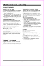
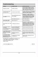
Page 19: ... the compressor build pressure in the tank to the maximum pressure if possible Brush soapy water on air connections and look carefully for air bubbles Tighten leaky connections If the problem persists contact the seller for further advice Let the air in the tank flow out until all the pressure is released Then remove the non return valve plug and clean the valve seal If necessary replace the seal ...

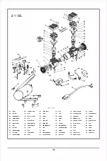
Page 20: ...6 pbt011 cup 16 fimd block 27 rilht fan mrt nitch Adjwit hol dlr indar plat 17 obturatinp in 28 shaft seal SafetJ a1 61 bolt 07 bolt 18 CODDectll IPipe 29 besrioa80 6 2Z bNrin 6209 2Z 51 11 08 CJlindm 19 bolt 41 dbratioacolma 02 11 09 obtuntill2Ii111 20 bolt SI bolt bolt 10 air filtl E 21 li mitedblock riaht cankcale Hlf tappfna C llhim foot 65 dn n l obturatiDP illl 22 al o protectionr lna capaci...

Page 21: ...2 1 SIL AL 20 ...

Page 22: ...r 18 valve plate 28 bolt 09 obturatingring 19 valve 29 bolt 10 obturatingring 20 washer 30 spring 31 rotator 32 33 stator 34 bearing6203 2Z 35 Abjustingwasher 36 vibrationcolnmn 37 spring 38 self tapping 39 air filter 40 elbow 21 41Deflationvalve 51unloading tube 61 42 regulator 52 pipe 62 43 40gauge 53 tank 63 44 5Ogauge 54handle sleeve 64 45 connect 55 nut 46 safety valve 56 washer 47pressureswi...

Page 23: ...1agnctlo vo1Tc55 washer 61 nut 62 drain cock 63 bolt 64 Pa nel 65 Support 06 Abjustingwasher 16 bolt 26 right fan 34 spring 35 rotator 36 stator 46 checkvalve 56 cushion foot 66 Adju t holder 07 bolt 17 spring 27 shaft seal 37 bearing6204 2Z 47 pipe 08 connectingrod 18 obLuralingring 28 bearing6908 2Z 38 vibra tioncolnmn 48 boll 09 piston cup 19 connecLingpipe 29 boll 39 spring 49 washer 57 washer...

Page 24: ......

Reviews: