background image

ISO


|

  10

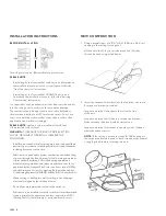
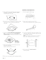
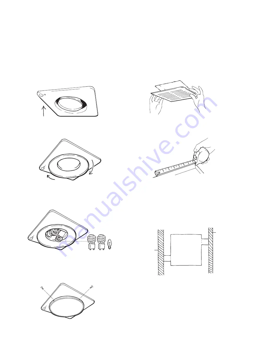
9  Pinch second mounting spring and give the ceiling panel 

a slight push to click into place. Ceiling panel should be  
mounted flush against the ceiling.

10  Push bell into center of ceiling panel to install. Give it a slight 

tug to make sure it does not pop off. It should be able to 
rotate freely.

11  Carefully install 

two (2) 13W (60W equivalent) GU24 CFL 

bulbs

 (not included) into the sockets and 

one (1) 7W C7 

incandescent bulb

 (not included) into the black center socket.

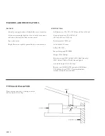
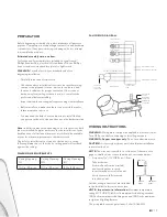
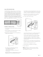
1  Remove existing fan and fan housing.

EXISTING CONSTRUCTION

2  Make sure the existing hole is at least 10” x 10”  

(25.4 cm x 25.4 cm) but smaller than 13” x 13” (33 cm x 33 cm).

3  Cut into the ceiling (about 2” [5 cm] wide to fit drill bit – refer 

to diagram) to extend suspension brackets and mount to stud 
(use a stud finder if necessary). 


NOTE: 

Save drywall piece to patch holes cut for suspension 

brackets after completing step 4 in New Construction.

4  Refer to Steps 2–13 in 

“New Construction” 

to 

complete installation.

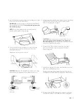
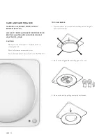
12  Attach metal trim glass dish to bell with the four (4) short 

machine screws (provided).

  Hardware used: Short machine screws x 4

13  Turn on electricity at breaker box after completing installation.

HOLE FOR FAN

JOIST

JOIST

10”

10”

2”

2”

Summary of Contents for ISO

Page 1: ...ilateur aspirant activ par la vapeur et veilleuse activ e par le mouvement extractor extractor activado por vapor y luz nocturna activada por movimiento ISO For service questions contact Quirky at 1 8...

Page 2: ...ISO 2...

Page 3: ...BOX SAFETY INFORMATION PREPARATION WIRING INSTRUCTIONS INSTALLATION INSTRUCTIONS NEW CONSTRUCTION EXISTING CONSTRUCTION WALL SWITCH SPECIFICATIONS CARE AND MAINTENANCE TROUBLESHOOTING WARRANTY UL507...

Page 4: ...SPECIFICATIONS Grill dimensions 13 x 13 x 1 5 33 cm x 33 cm x 3 8 cm Housing dimensions 97 8 x 97 8 x 8 25 1 cm x 25 1 cm x 20 3 cm Duct diameter 4 10 2 cm Sound output 1 3 sones Airflow 90 CFM Exhau...

Page 5: ...ng wood screw 6 actual size short machine screw 4 actual size long machine screw 2 actual size switch suspension bracket II suspension bracket III metal rim and glass bell ceiling plate IN THE BOX NOT...

Page 6: ...control dimmer switch or certain timers Mechanical timers are not solid state devices Do not install in a cooking area CAUTION For general ventilating use only do not use to exhaust hazardous or explo...

Page 7: ...rdware store The hole for installation is not sized to the fan unit use the following dimensions so that the Iso ceiling panel will rest flush against the ceiling DIMENSION REQUIREMENTS Ceiling Openin...

Page 8: ...n s in accordance with all applicable codes and standards including fire rated construction Sufficient air is needed for proper combustion and exhausting of gases through the flue chimney of fuel burn...

Page 9: ...BOARD CEILING BOARD JOIST BRACKET 5 Using wire nuts provided connect house wires to ventilating fan wires black to black white to white green to green refer to wiring diagram on page 7 CAUTION If you...

Page 10: ...housing EXISTING CONSTRUCTION 2 Make sure the existing hole is at least 10 x 10 25 4 cm x 25 4 cm but smaller than 13 x 13 33 cm x 33 cm 3 Cut into the ceiling about 2 5 cm wide to fit drill bit refer...

Page 11: ...al wire which is white and potentially a grounding wire which is green or bare copper There may be other wires in the switch box but you are only dealing with the ones connected directly to the switch...

Page 12: ...use solvents thinner or harsh chemicals for cleaning the fan Do not allow water to enter the motor Do not immerse plastic parts in water over 140 F 60 C 1 Unscrew the four 4 screws and carefully remov...

Page 13: ...cloth with dish detergent wipe the fan housing and dry with a cloth DO NOT USE abrasive cloth steel wool pads or scouring pads 3 Replace the ceiling panel by following steps 7 13 under installation i...

Page 14: ...n 18 45 7 cm to the fan discharge Fan body not securely attached Be sure the fan is securely attached to your ceiling joists Fan duct is being obstructed at some point including end of duct Check the...

Page 15: ...Night light sensor is not registering movement Using a damp cloth or rag clean off fan s faceplate including the small half sphere sensor Make sure the hanging part of the unit is not obstructing the...

Page 16: ...implied warranties or incidental consequential or other damages so the above exclusions and limitations may not apply to you This device complies with Part 15 of the FCC Rules Operation is subject to...

Page 17: ...ection 64A Installation Instructions WARNING TO REDUCE THE RISK OF FIRE ELECTRIC SHOCK OR INJURY TO PERSONS OBSERVE THE FOLLOWING a Installation work and electrical wiring must be done by qualified pe...

Page 18: ...or service and support email us at questions quirky com or call 1 866 5QUIRKY 1 866 578 4759 R INS ISO1 X rev073014 For service questions contact Quirky at 1 866 578 4759 For sales inquiries contact S...

Reviews: