

ISO
|
11
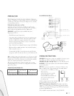
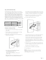
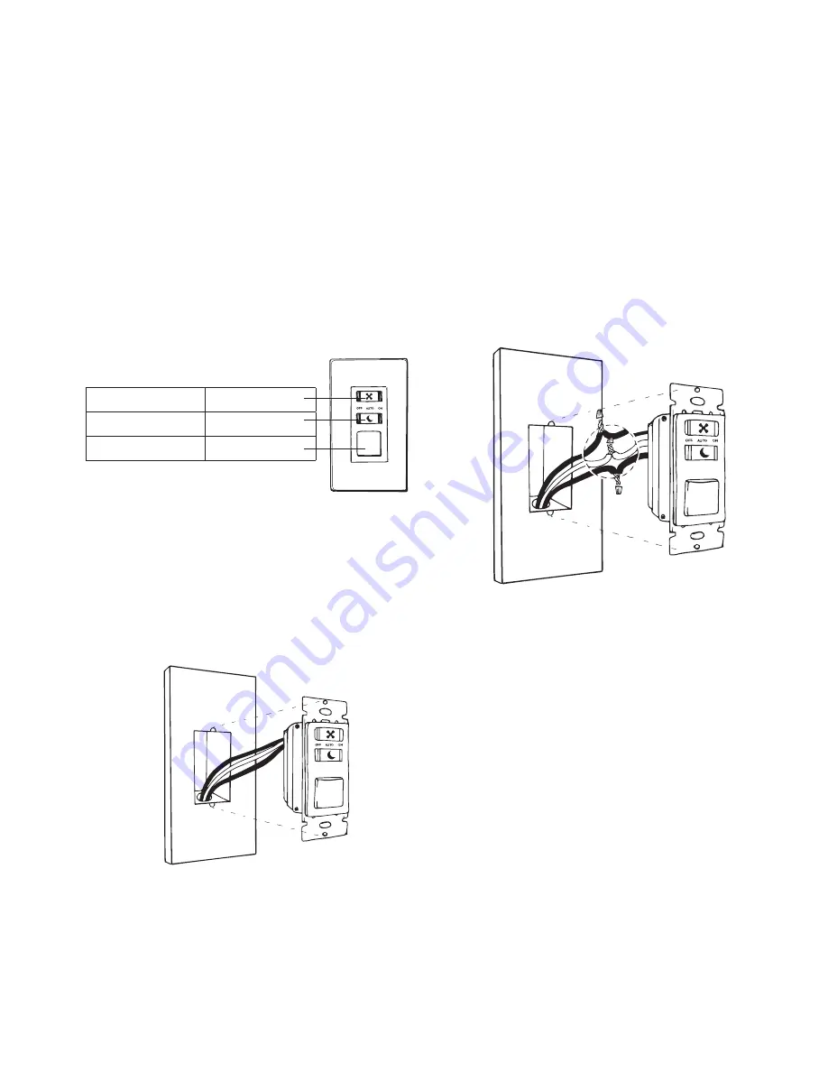
WALL SWITCH SPECIFICATIONS
The wall switch has two sliding switches: one for the fan and
one for the night light. There is also a button for the main lights.
The fan and night light sliding switches have three positions:
off/auto/on. In “auto” mode, the fan turns on when the humidity
sensor senses sufficient humidity, and the nightlight turns on
when the motion detector detects motion in a dark environment.
The humidity and motion detectors are built into the ceiling
component. In “on” mode, the fan and nightlight remain on even
if the room is not humid and no motion is detected. The main light
button clicks on and off; it has no “auto” mode.
Switch (Fan)
ON/OFF/AUTO
Switch (Night Light)
ON/OFF/AUTO
Button (Main light)
ON/OFF
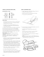
TO INSTALL THE WALL SWITCH
1 Turn off the power to the switch at the main circuit breaker
or fuse panel.
2 Unscrew and remove the switch plate; then use a voltage
tester to make sure that the circuit is dead.
3 Unscrew the switch from the electrical box and pull it out
with the wires still attached.
• Two or three wires will be attached to the switch:
– an incoming hot wire, which is black;
– a neutral wire, which is white;
– and potentially, a grounding wire, which is green
or bare copper.
• There may be other wires in the switch box, but you are only
dealing with the ones connected directly to the switch.
• You may find a white wire that has black tape on it connected to
the switch. This tape indicates that the white wire is being used
as a black or colored wire in the switch leg, so it is not neutral.
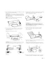
4 Compare your new switch with the one you’re replacing
to find the corresponding locations for the wires.
5 To connect wires to the new switch:
• Locate the black (hot) wire in your switch box and attach to the
black wire in the new switch using a wire nut (provided).
• Locate the white (neutral) wire in your switch box and attach
to the white wire in the new switch using a quick connector.
• Locate the ground (green or copper) wire in your switch box
and attach to the ground wire in the new switch using a wire nut
or quick connector.
6 Gently push the new, wired switch back into the switch box and
screw the switch plate in place using the provided machine screws.
Hardware used: CC Long machine screw x 2
7 Attach faceplate (not included) over switch plate.
8 Turn on the power.
NOTE:
The wall switch communicates wirelessly with the
fan/ light unit. Therefore, no wires are run from the switch
to the fan/light unit in the ceiling.
Summary of Contents for ISO
Page 2: ...ISO 2...


