


ISO
|
14
TROUBLESHOOTING TIPS
PROBLEM
POSSIBLE CAUSES
WHAT TO DO
THERE IS A VISIBLE
GAP BETWEEN THE
CEILING PANEL AND
CEILING
The hole is smaller than
10” x 10” (25.4 cm x 25.4 cm)
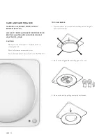
Remove panel (refer to Care & Maintenance) and check to see
if fan was installed properly
Bottom edge of fan is
less than 3⁄4” (1.9 cm) from
ceiling surface
Remove panel (refer to Care & Maintenance) and check to see
if fan was installed properly
THE FAN SEEMS
LOUDER THAN IT
SHOULD BE
CFM too high
90 CFM fan is designed for rooms up to 100 sq ft (9.3 sq m)
Damper (exhaust port)
not working properly or
is damaged.
Check exhaust flap to ensure it is opening and closing properly.
If the exhaust fan has become damaged, please call Customer
Service
Bend in duct too close
to fan discharge.
Be sure you do not have any sharp bends in duct closer
than 18” (45.7 cm) to the fan discharge
Fan body not securely
attached.
Be sure the fan is securely attached to your ceiling joists
Fan duct is being obstructed
at some point (including end
of duct)
Check the air duct to ensure the duct is not restricting air flow
Fan may be clogged with
dust or debris
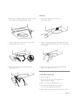
Refer to Care & Maintenance section for cleaning instructions
THE FAN IS NOT
CLEARING THE
HUMIDITY OUT
OF THE ROOM.
Insufficient intake airflow
within room.
The fan is not able to draw air out of the room without enough
airflow to draw from have a door or window slightly ajar or open
to allow airflow
Insufficient CFM
Be sure the CFM rating on the fan matches the requirements
for your room size.
NOTE:
If the fan clears steam from the room
within 15 minutes after the shower has been turned off, the fan is
operating properly
Dust/dirt is clogging
fan intake
Refer to Care and Maintenance instructions
Duct may not be connected
to fan properly
Check air duct and fan connection to ensure that there
is a proper seal
Summary of Contents for ISO
Page 2: ...ISO 2...


