


ISO
|
15
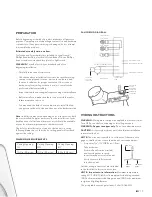
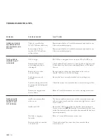
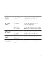
PROBLEM
POSSIBLE CAUSES
WHAT TO DO
THE FAN IS NOT
TURNING ON IN
“AUTO” MODE
Humidity sensor PCB is not
connected
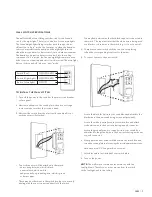
Please revisit the instruction manual and verify the wiring
of the wall switch and fan are properly connected
Sensor PCB was connected
while power was on
With sensor PCB still connected, restart power source
to the unit
NIGHT LIGHT NOT
TURNING ON
Sensor is obstructed
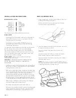
Using a damp cloth or rag, clean off the fan’s faceplate,
including the small half sphere sensor
Bulb is burnt out
Check and replace night light bulb
Night light sensor is not
registering movement
Using a damp cloth or rag, clean off fan’s faceplate, including the
small half sphere sensor. Make sure the hanging part of the unit
is not obstructing the PIR sensor from detecting movement
THE REGULAR LIGHT
IS NOT TURNING ON
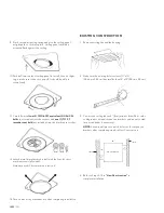
Bulb is burnt out
Check and replace light bulb using the instructions on page 13
Wiring could have
become loose
Check switch box wiring to ensure wiring is correct
THE FAN IS NOT
TURNING OFF
Humidity in the room is
still in target range for
fan to stay activated
Turn off manually or wait for fan to re-calibrate
WATER DAMAGE/
LEAKING ON CEILING
The vent/duct has
not been installed
correctly
Make sure the vent/duct is venting outward and not up
into the ceiling
Summary of Contents for ISO
Page 2: ...ISO 2...


