Technical description |
EN
2 Technical description
Network Node Q
node
5.5 receive and distribute the data from consumption meters (maximum 500) within the Q AMR-
System. Several network nodes (maximum twelve) form a network. Different types of network nodes exist for the
various use cases. All types can be combined with each other in a network.
2.1 Assemblies Q
node
5.5
The network node Q
node
5.5 consists of the following assemblies:
•
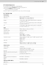
Power supply
– Battery for RNN5
000M
0x
– Power supply unit for RNN5
000M
1x
•
Transmitter/receiver for Q AMR network
•
Memory
– 500 devices
•
Interfaces
– M-Bus (Slave)
– IrDA (optical)
– RS232* (RNN5
000M
1x)
•
Backup battery
(* The network nodes RNN5
000M
1x have an additional RS232 interface for readout)
Transmitter and receiver are used for data acquisition from consumption meters and forwarding to other network
nodes in the same network. The data memory holds the measured values of the consumption devices. It is protected
against a temporary failure of the supply voltage, for example when the main battery is changed, by the backup
battery. A local readout of the network can be made via the M-Bus interface (an M-Bus load).
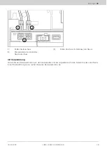
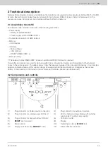
2.2 Components and controls
(1)
Plug connector for M-Bus service connection
(2)
Plug connector for extension module
(3)
Plug connector for voltage supply DC 3.6 V
(4)
LED for network voltage display with external
supply (only lit during mains supply)
(5)
Plug connector for backup battery DC 3.6 V
(6)
Connector outlet
(7)
RESET
key (recessed)
(8)
Display
(9)
Serial number
(10)
Operating mode key (
MODE
, red)
(11)
Display switchover key (
DISPLAY
, blue)
(12)
Infrared interface (optical)
09.03.2023
55


