background image

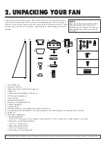
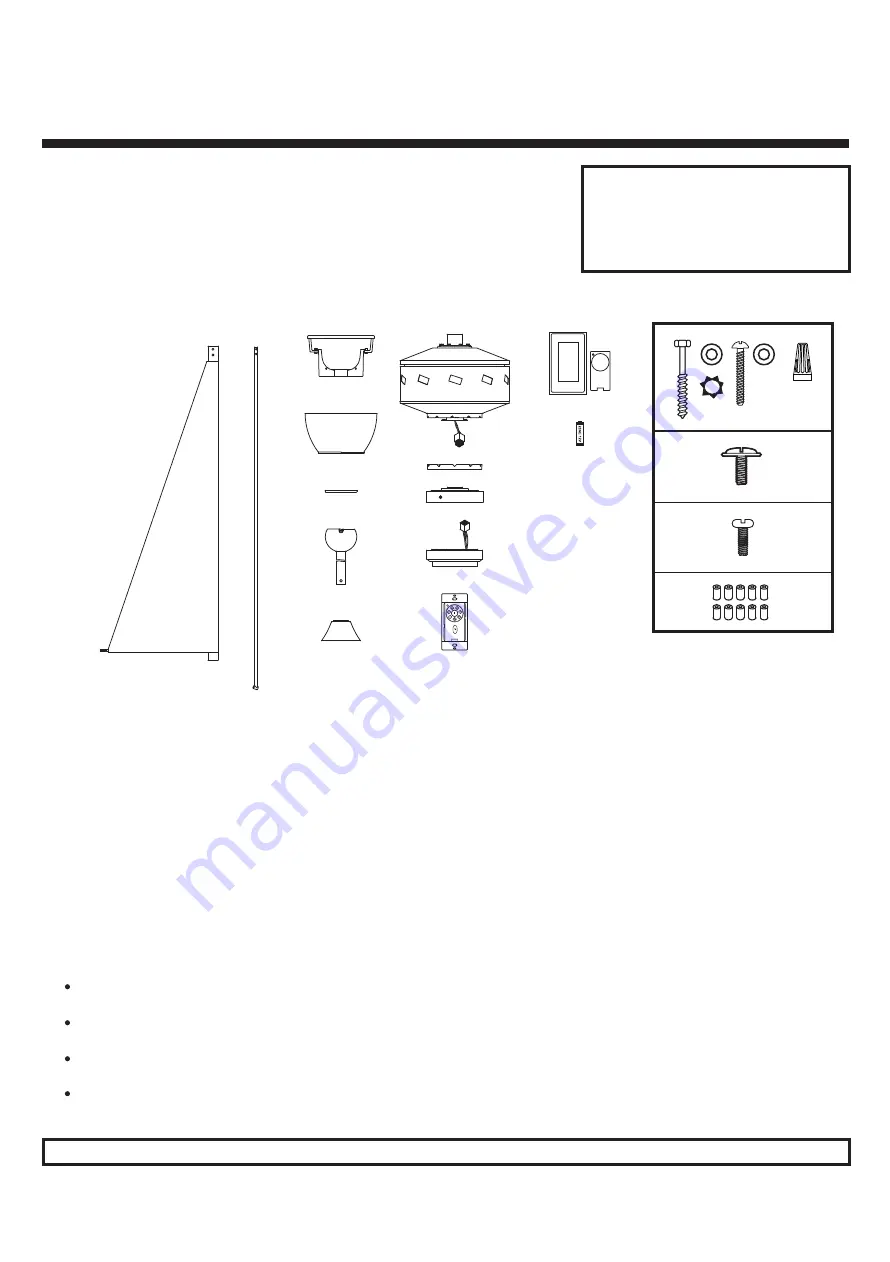
1.   Set of blades (a)
2.   Decorative rods (b)
3.   Hanger bracket (pre-installed in canopy) (c)
4.   Canopy (d)
5.   Canopy cover (pre-installed in canopy) (e)
6.   10" Downrod assembly (f)
7.   Yoke cover (g)
8.   Fan motor assembly (h)
9.   Decorative rod support plate (i)
10. Control cup plate (j)
11. Control cup (k)
12. Wall transmitter incl. 2 mounting screws and 3 wire nuts (l)
13. 2 wall plates (white and almond), 1 face plate (almond), 2 sets of mounting screws, and machine screws (m)
14. Battery (n)
15. Parts bags containing (o)

Mounting hardware 
(2 #14x3.5" wood screws, 2 star washers, 2 metal washers, 1 #12x3" wood screw, 1 metal washer, 3 wire nuts,)

         Decorative rod attachment hardware

(21 5/32 x 19mm Screws)

         Blade attachment hardware

(21 3/16 x 24mm Screws)

         10 Decorative rod mounting nuts

Unpack your fan and check the contents.  Do not discard the carton. If warranty replacement or 
repair is ever necessary the fan should be returned in original packaging.  Remove all parts and 
hardware.  Do not lay motor housing on its side - because the decorative casing may shift.  Check 
all visible screws, bolts and nuts for tightness.  Examine all parts.  The following parts should be 
included:

2. UNPACKING YOUR FAN

NOTE:

Some Quorum fan models will have slightly 
different parts than what is shown here 
depending upon the design you have chosen.  
Basic installation procedures are similar for 
all models.

IF YOU FIND THAT PARTS ARE MISSING. CONTACT YOUR DEALER FOR REPLACEMENT, OR CALL QUORUM DIRECTLY AND WE WILL MAIL REPLACEMENTS TO YOU IMMEDIATELY.

c.

d.

e.

f.

g.

h.

i.

j.

k.

l.

m.

n.

o.

a.

b.

Summary of Contents for Mykonos 72"

Page 1: ...and save these instructions These instructions are to be used in the installation of the following QUORUM INTERNATIONAL fans The Mykonos 72 92 P O Box 961008 Fort Worth TX 76161 817 626 5483 FAX 817...

Page 2: ...stions regarding the warranty or the procedures for obtaining service please call us at 817 626 5483 Monday thru Friday 8 00 a m 5 00 p m CST technical skill competence or experience of the user 8 Lig...

Page 3: ...for the blades to rotate and at lease seven 7 feet of clearance between the floor and the fan blade tips 5 The support structure must be securely mounted and capable of reliably supporting a minimum...

Page 4: ...Blade attachment hardware 21 3 16 x 24mm Screws 10 Decorative rod mounting nuts Unpack your fan and check the contents Do not discard the carton If warranty replacement or repair is ever necessary the...

Page 5: ...ructure Use appropriate fasteners and building materials 4 Figures 1 2 and 3 are examples of different ways to mount the outlet box in different situations A longer downrod may be required in sloped c...

Page 6: ...screws on the hanger bracket to apart the hanger plate and neck of the hanger bracket mounting neck Fig 7 7 Remove stop valve from the neck of the hanger bracket by loosening the two stop valve screws...

Page 7: ...will lower down to conceal the yoke Feed the safety cable and wires through the downrod assembly 3 Fig 11 Lift the fan motor and place into the hanger bracket rotating the ball until the groove engag...

Page 8: ...onnect the wiring from the wall switch receptacle to wall transmitter unit Remove the existing wall plate and switch from the wall junction box Connect the BLACK switch leg wire from wall receptacle t...

Page 9: ...other screw hole in the rod aligns with the inside hole in the decorative rod holder as it will be used later Repeat process for all other rods Once completed tighten the decorative rod nuts on end of...

Page 10: ...revent damage to transmitter remove the battery if not use for long periods of time Fig 20 A I II III IV V and VI buttons These six buttons are used to set the fan speed as follows I minimum speed II...

Page 11: ...peration for many years 5 If repairs or servicing are ever required to avoid possible electric shock turn off the electricity at the main fuse or circuit panel before you begin 9 FAN OPERATION AND CAR...

Page 12: ...ut connectors are not resting against the canopy possibly vibrating while the fan is on 3 Use of a standard light rheostat or an unapproved fan wall control to control the fan speed will always cause...

Reviews: