
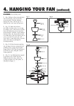

Fig. 6
Fig. 7
Fig. 8
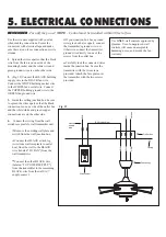
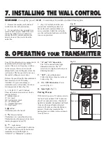
WARNING -
Turn off the power!
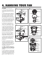
1.
Remove the motor top housing and
metal washer by remove the six screws
with lock washers from the motor collar.
(Fig. 4)
2.
Insert the blade assembly through the
slot in the motor housing. Carefully insert
blade to blade arm on top of the motor.
Align the holes in the blade and the fan
motor assembly and secure with 2 screw
provided. Tighten screws securely. (Fig. 5)
3.
Place the motor top housing over the
motor. Align the mounting holes with the
holes in the motor and fasten using the six
screws with lock washers and metal
washer previously removed. (Fig. 5)
4.
Remove the canopy bottom cover
from the canopy by turning the canopy
bottom cover counterclockwise. (Fig. 6)
5.
Remove the hanger bracket from the
canopy by removing the non-slotted
canopy mounting screw from the bottom
of the canopy and loosening the slotted
canopy mounting screw a half turn from
the screw head. Next, turn the canopy
counterclockwise to remove the hanger
bracket from the canopy. (Fig. 6)
6.
Unscrew the four neck of the hanger
bracket screws on the hanger bracket to
apart the hanger plate and neck of the
hanger bracket (mounting neck). (Fig. 7)
7.
Remove stop valve from the neck of
the hanger bracket by loosening the two
stop valve screws on the neck of the
hanger bracket in 1/4" from the screw
head. (Fig. 7)
8.
Remove two knock-outs from the
outlet box to expose the joist. Use the two
wood screws and washers provided to
secure the hanger bracket directly to the
building joist via the knockout holes from
the outlet box. Securely tighten the two
mounting screws. (Fig. 8)
CAUTION:
The hanger bracket must
be installed directly to the building joist
using the two wood screws and washers
provided.
9.
Attach mounting neck onto the hanger
bracket. You have to rotate the mounting
neck to align the four screw holes, Secure
mounting neck to the hanger bracket with
four neck of the hanger bracket screw to
become a complete hanger bracket. (Fig.
8)
4. HANGING YOUR FAN
Fig. 4
Fig. 5
Screws
Metal washer
Top housing
Yoke
Screws
Blades
Screws
Metal washer
Top housing
Yoke
Hanger
bracket
Canopy
Screw
Screw
Canopy
cover
Hanger
bracket
Mounting
neck
Screws
Screw
Stop valve
Outlet box
#14x3.5"
Wood screws
Hanger
bracket
Mounting
neck
Star washers
Metal washers
Knock out
Neck of the
hanger
bracket screws


