
Fig. 11
WARNING -
Turn off the power!
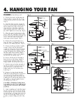
1.
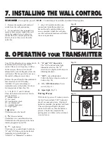
(Fig. 9) Remove the set pin and safety
lock clip from the yoke on top of the
motor assembly. Slide the downrod
through the canopy and canopy cover.
Slide the yoke cover onto the downrod.
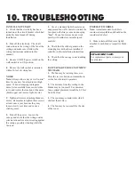
2.
(Fig. 10) Attach the downrod
assembly (downrod, yoke cover, canopy
and canopy cover) to the motor by sliding
the downrod into the yoke on top of the
motor assembly. Slide the set pin through
the hole in the yoke, downrod and secure
it with the safety lock clip. Tighten the set
screws on yoke. The yoke cover will
lower down to conceal the yoke. Feed the
safety cable and wires through the
downrod assembly.
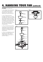
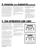
3.
(Fig. 11) Lift the fan motor and place
into the hanger bracket, rotating the ball
until the groove engages the tab on the
hanger bracket. This locks the ball mount
and fan motor, preventing fan rotation
during operation.
4.
(Fig. 11) An additional safety support
is provided to prevent the fan from
falling. Secure the safety cable to the
ceiling joist with screw and washer, as
illustrated in Figure 11.
4. HANGING YOUR FAN
(continued)
Fig. 9
Downrod
assembly
Ceiling
canopy
Canopy
cover
Yoke cover
Fig. 10
Downrod
Set screw
Yoke
Safety
lock clip
Set pin
Canopy
Canopy cover
Yoke cover
Downrod
Hanger bracket
Safety cable
Safety cable


