1.
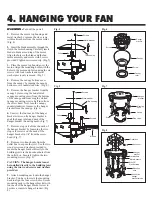
Make sure the wiring is safely inside the
outlet box as instructed in
Step 5 -
Electrical Connections.
To install the
canopy, slide the canopy up to hanger
bracket and place the key hole on the
canopy over the screw on the hanger
bracket, turn canopy until it locks in place
at the narrow section of the key holes. (Fig.
13) Align the circular hole on canopy with
the remaining hole on the hanger bracket,
secure by tightening the two set screws, lift
canopy cover and attach by turning
clockwise.
Note:
Adjust the canopy screws
as necessary until the canopy and canopy
cover are snug. (Fig. 13)
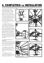
2.
Installing the Decorative rods
Remove decorative rod nut from blade end
and slide the decorative rod onto the blade
end screw. Attach the decorative rod nut
loosely - do not tighten at this time (Fig. 14).
Align the opposing end of the rod with holes
in the decorative rod holder and attach screw
by passing through the rod to attach to the
outer hole in the decorative rod holder and
tighten (Fig. 15). Be sure the other screw
hole in the rod aligns with the inside hole in
the decorative rod holder as it will be used
later. Repeat process for all other rods. Once
completed, tighten the decorative rod nuts on
end of blades.
3.
Installing the Decorative Rod
Support plate
Place the decorative rod support plate up to
the motor. Align holes from the support plate
and rod and secure with the ten decorative
rod screw in inner holes. Make sure all
screws are tightened securely. (Fig. 16)
4.
Attaching the Control Cup Plate
Attach the control cup plate to the flange of
the motor by using the three screws
provided that are pre-installed on the flange.
(Fig. 17)
5.
Attaching the Control Cup
Snap together the cannon plugs, attach the
control cup to the control cup plate with the
three screws provided. (Fig. 18)
6. COMPLETING
THE
INSTALLATION
Fig. 16
Fig. 13
Outlet box
Hanger
bracket
Canopy
Canopy cover
Screws
Screws
Fig. 17
Screws
Fiange
Control
cup plate
Fig. 18
Screws
Control
cup
Control
cup plate
Cannon plug
Decorative rod
screws
Decorative rod
support plate
Decorative
rod holder
Fig. 14
Decorative rod
Nut
Blade end
Blade end
screw
Fig. 15
Decorative
rod holder
Inner
hole
Decorative rod screws
Decorative rod
Outer hole


