


W A RN I N G
- Turn off the power!
REM EM BER
- Turn off the power!
DO NOT fasten the blades to the fan
until it is assembled and hanging from
the ceiling. To do so now will likely
bend the blade arms and almost cer-
tainly cause wobble.
1.
If not already affixed to the hanger
bracket, place the rectangular rubber
isolators between the hanger bracket and
outlet box. Secure the hanger bracket to
the outlet box using the 2 long steel
screws supplied with the fan.
2.
Remove the set pin and safety lock
clip from the downrod/ball assembly.
(Fig. 5) Slide the downrod through the
canopy, hanging bar hooks (use only if
12" downrod is used) and yoke cover.
Feed the wires from the fan motor
through the downrod assembly.
3.
(Fig. 6) Attach the downrod
assembly to the motor by sliding the
downrod into the yoke on top of the
motor assembly. Slide the set pin through
the hole in the yoke, downrod and wash-
er and secure it with the safety lock clip.
Tighten the set screws on yoke. Cover
with yoke cover.
4.
Lift the fan motor without the blades
and place into the hanger bracket, rotat-
ing the ball until the groove engages the
tab on the hanger bracket. This locks the
ball mount and fan motor, preventing fan
rotation during operation.
Use the wires nuts supplied with your
fan when making connections. Secure
the connectors with electrical tape and
make sure there are no loose connections
or wire strands.
• Connect the other BLACK wire from
the transmitter to the remaining
BLACK wire from the wall (A/C sup-
ply source).
5.
If your junction box has a ground
wire (Green or bare Copper), connect the
transmitter ground wire to it. Otherwise,
connect the transmitter ground wire
directly to one of the screws from the
outlet box.
6.
Before mounting the wall transmit-
ter, be sure to check the DIP switch set-
ting to be sure they match the setting
selected on the receiver unit.
7.
Carefully tuck the connected wires
inside the junction box. Secure the wall
transmitter with the two screws provided.
Attach the faceplate over the transmitter
1.
Make wire connections from the fan
to the wall control receiver unit. For this
step use the bundle of 4 wires on the
canopy receiver. (Fig. 7).
• Connect the BLACK fan wire to the
BLACK receiver wire.
• Connect the BLUE fan wire to the
BLUE receiver wire.
• Connect the WHITE fan wire to the
WHITE receiver wire.
• Connect the ORANGE fan wire to the
ORANGE receiver wire.
2.
Connect the wiring from the ceiling
to the canopy receiver. (Use the 2 wire
bundle on the receiver.)
• Connect the BLACK building supply
wire to the BLACK receiver wire.
• Connect the WHITE building supply
wire to the WHITE receiver wire.
• Connect the COPPER building
ground wire to the GREEN fan
ground wire.
3.
Before securing the ceiling canopy,
select the switch code setting with the
DIP switches on the canopy receiver.
Note that at least one of the 4 DIP
switches must be in the “on” position.
Also note the DIP switches on the wall
transmitter unit must be set the same as
on the receiver unit.
4.
Connect the wiring from the wall
switch receptacle to wall transmitter unit.
• Remove the existing wall plate and
switch from the wall junction box.
• Connect one BLACK wire from the
wall to one Black wire (labeled “ TO
FAN ”) from the wall transmitter.
with the two White screws provided.
Note:
This wall control and receiver unit
has 16 different code combinations. Your
fan will not operate if the switch settings
do not match. If you have another remote
operated fan in your home, make sure
the DIP switch setting you have selected
will not interfere with your existing fan.
If it does, simply change the DIP switch
settings in both the canopy receiver unit
and wall transmitter unit.
B
L
K
W
H
G
ro
u
n
d
B
L
U
B
L
K
W
H
O
R
A
N
G
E
G
R
N
B
L
U
B
L
K
W
H
O
R
N
G
B
L
K
W
H
BLK
BLK
BLK
BLK
GRN
Fig. 7
Use ONLY wall controls approved
by Quorum. Use of unapproved wall
controls will cause unacceptable
humming noise, and voids the fan
warranty.
Fig. 5
Downrod
Canopy
Hanging Bar Hooks
Yoke Cover
Fig. 6
Downrod
Assembly
Washer
Yoke
Set Screws
Yoke
Safety
Lock Clip
Set Pin
W A RN I N G
- To reduce the risk of shock, fire or injury, mount the fan ONLY to
an outlet marked “Acceptable for Fan Support”.
1.
Disconnect the power by removing
fuses or turning off circuit breakers.
2.
If there is an existing outlet box,
ensure it is clearly marked “Suitable For
Fan Support”. If it is not so marked, it
must be replaced with an approved one.
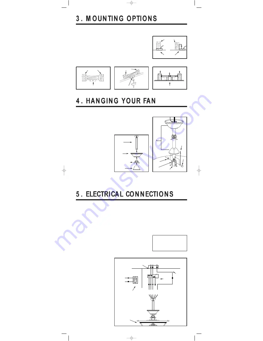
3.
Secure the outlet box (or make sure
the existing box is secured) directly to
the building structure. Use appropriate
fasteners and building materials.
4.
Figures 1, 2 and 3 are examples of
different ways to mount the outlet box in
different situations. A longer downrod
may be required in sloped ceiling situa-
tions to maintain proper blade clearance.
5.
To hang the fan in locations where
no ceiling joist is available, a hanger
support bar may be required (Fig. 4).
Quorum distributes approved hanger
support bars and outlet boxes.
Fig. 1
Ceiling Joists
Outlet Boxes
Fig. 2
Ceiling Joists
Outlet Box
Fig. 3
Ceiling Joists
Recessed Outlet Box
Fig. 4
Ceiling Joist
Hanger
Support Bar
Ceiling Joist
Outlet Box
Outlet Box
Ceiling
Wall
Transmitter
Canopy
Receiver
Fan
Salon Inst -10_03-ok 6/9/2005 2:33 PM Page 3


