Q150T Sample Preparation System
Q150T - Instruction Manual
65
10473 - Issue 5
7.7
Slide Stage
To install the slide sample stage (10358):
1.
Check the machine is not operating.
2.
Open the top cover fully so it rests against its backstop.
3.
Remove any installed stage by lifting carefully upwards.
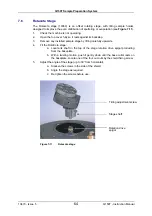
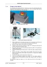
Figure 7-12.
Slide stage
4.
If necessary, adjust the stage height above the base plate:
a.
Slacken the M3 screw in the collar with a hexagonal key.
b.
Slide the collar to the desired position and retighten the M3 screw.
The recommended position for the collar is to achieve a 31.5mm distance
between the underside of the collar and the underside of the stage. If you require a
greater distance between the stage and the target, the collar can be removed
altogether with the underside of the stage therefore resting on the top of the drive
spigot.
An alternative shaft is supplied with the stage (10214) to further increase the
range of stage height adjustment available. To fit, hold the stage firmly and
release the M5 nut. Unscrew the shaft, transfer the nut to the new shaft and fit to
the stage so that the top is flush with the lower surface of the stage when the nut is
tightened.
5.
Fit the slide stage:
a.
Locate its shaft in to the top of the stage rotation drive spigot protruding
from the base plate.
b.
With a twisting motion, push gently down until the collar around the shaft
rests on top of the drive spigot (see
Figure 7-12
).
Remove the collar if you need more distance between the stage and the target:
the underside of the stage then rests on the top of the drive spigot.
To maximise the area or achieve more uniform coating on the slide stage, install the
stage gearbox assembly (10359) – see page 66.
Slide sample stage
Height-adjusting collar
Stage shaft
Rotation drive
spigot
Summary of Contents for Q150T S
Page 92: ......

