background image

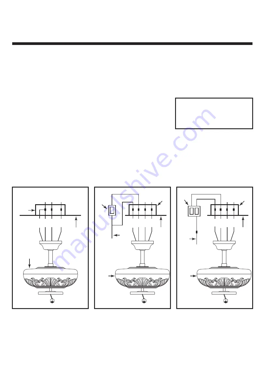
5. ELECTRICAL CONNECTIONS

Fig. 8

Fig. 8a

Fig. 8b

Outlet box

Fan switch
on wall

Ceiling

REMEMBER 

-Turn off the power!

WH

BLUE

BLK

WH

BLK

House 
supply 
wire

GROUND

GRN

3. Optional Wall Controls: 
Wiring connections for optional wall 
control are shown in Fig. 8a and 8b. Figure 
8a shows how to wire a fan wall control 
switch. This controls the fan only.  To 
separately control an optional light kit 
using the light kit pull chain, you would 
have to connect the blue wire from the fan 
to the house supply wire, before it goes to 
the wall control.  This is not an easy 
connection, and we suggest you call a 
qualified electrician to do it for you.

4. Inside the ceiling junction box be sure 
to spread the wires apart so that the black 
and blue connections are on one side of 
the outlet box and the white/white and 
green/ copper connections are on the other 
side.

Use the wire nuts supplied with your fan 
when making connections.  Secure the 
connectors with electrical tape and make 
sure there are no loose connections or wire 
strands.

1. Spread the wires apart so that the black 
and blue wires from the fan are on one 
side of the mounting bracket and the white 
wire and green ground wire are on the 
other side.

2. (Fig. 8) Connect the BLACK building 
supply wire to the BLACK and BLUE fan 
wires. Connect the WHITE building 
neutral wire to the WHITE fan neutral 
wire. Connect the COPPER building 
ground wire to the GREEN fan ground 
wire.

Use 

ONLY

 wall controls approved by 

Quorum. Use of unapproved wall 
controls will cause unacceptable 
humming noise, and avoids the fan 
warranty.

Outlet box

Ceiling

WH

BLUE

BLUE

BLUE

BLK

WH

BLK

BLK

BLK

GROUND

GRN

Fan/light 
switch
on wall

House 
supply 
wire

Outlet box

Ceiling

WH

BLUE

BLUE

BLUE

BLK

WH

BLK

BLK

BLK

BLK/WH

GROUND

GRN

Fan 

Fan 

Fan 

Summary of Contents for The Chateaux 52"

Page 1: ...ns are to be used in the installation of the following QUORUM INTERNATIONAL fans The Chateaux 52 60 Uni Pack 2014 P O Box 961008 Fort Worth TX 76161 817 626 5483 FAX 817 626 5540 IO221 03 14 THE CHATE...

Page 2: ...stions regarding the warranty or the procedures for obtaining service please call us at 817 626 5483 Monday thru Friday 8 00 a m 5 00 p m CST technical skill competence or experience of the user 8 Lig...

Page 3: ...l before you begin the fan installation or before servicing the fan or installing accessories 2 Read all instructions and safety information carefully before installing your fan and save these instruc...

Page 4: ...blade clearance 5 To hang the fan in locations where no ceiling joist is available a hanger support bar may be required Figure 4 Quorum distributes approved hanger support bars and outlet boxes 3 MOUN...

Page 5: ...the yoke on top of the motor assembly Slide the downrod through the canopy Fig 5 Feed the wires from the fan motor through the downrod assembly 3 Fig 6 Attach the downrod assembly downrod and canopy t...

Page 6: ...the white white and green copper connections are on the other side Use the wire nuts supplied with your fan when making connections Secure the connectors with electrical tape and make sure there are...

Page 7: ...mbly under your fan snap together the wire connection plugs Carefully push all wires back into the control cup then install the light kit assembly onto the control cup plate with 3 screws provided Be...

Page 8: ...Periodically check tightness of all screws securing the blades to the blade arm attachment points A clicking or a rattling noise is a sure indication of loosening screws Since screws will invariably w...

Page 9: ...always cause an annoying hum Many fan motors do not work quietly with solid state variable speed controls 4 Check that the rubber gasket on the mounting bracket has been installed if called for in the...

Reviews: