

3. MOUNTING OPTIONS
WARNING
- To reduce the risk of shock, fire or injury, mount the fan ONLY to
an outlet marked “Acceptable for Fan Support”.
4. HANGING YOUR FAN
5. ELECTRICAL CONNECTIONS
WARNING
- Turn off the power!
REMEMBER
- Turn off the power!
1.
Disconnect the power by removing
fuses or turning off circuit breakers.
2.
If there is an existing outlet box,
ensure it is clearly marked “Suitable For
Fan Support”. If it is not so marked, it
must be replaced with an approved one.
3.
Secure the outlet box (or make sure
the existing box is secured) directly to
the building structure. Use appropriate
fasteners and building materials.
4.
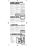
Figures 1, 2 and 3 are examples of
different ways to mount the outlet box in
different situations. A longer downrod
may be required in sloped ceiling situa-
tions to maintain proper blade clearance.
5.
To hang the fan in locations where
no ceiling joist is available, a hanger
support bar may be required (Fig. 4).
Quorum distributes approved hanger
support bars and outlet boxes.
Fig. 1
Ceiling Joists
Outlet Boxes
Fig. 2
Ceiling Joists
Outlet Box
Fig. 3
Ceiling Joists
Recessed Outlet Box
Fig. 4
Ceiling Joist
Hanger
Support Bar
Ceiling Joist
Outlet Box
DO NOT fasten the blades to the fan
until it is assembled and hanging from
the ceiling. To do so now will likely
bend the blade arms and almost cer-
tainly cause wobble.
1.
If not already affixed to the hanger
bracket, place the rectangular rubber
isolators between the hanger bracket and
outlet box. Secure the hanger bracket to
the outlet box using the 2 long steel
screws supplied with the fan.
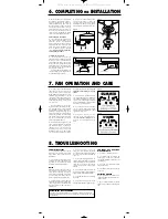
2.
Remove the set pin and safety lock
clip from the downrod/ball assembly.
Slide the downrod through the canopy
Slide the yoke cover onto the downrod
(Fig. 5). Feed the wires from the fan
motor through the downrod assembly.
3.
(Fig. 6) Attach the downrod assem-
bly (downrod, yoke cover and canopy)to
the motor by sliding the downrod into
the yoke on top of the motor assembly.
Slide the set pin through the hole in the
yoke, downrod and washer and secure it
with the safety lock clip. Tighten the set
screws on yoke. The yoke cover will
lower down to conceal the yoke. Feed
the wires through the downrod ball
gasket.
4.
Lift the fan motor without the blades
and place into the hanger bracket, rotat-
ing the ball until the groove engages the
tab on the hanger bracket. This locks the
ball mount and fan motor, preventing fan
rotation during operation.
Fig. 6
Fig. 5
Downrod
Ball Gasket
Downrod
Assembly
Washer
Yoke
Safety
Lock Clip
Downrod
Canopy
Yoke Cover
Use the wires nuts supplied with your
fan when making connections. Secure
the connectors with electrical tape and
make sure there are no loose connections
or wire strands.
1.
Spread the wires apart so that the
black and blue wires from the fan are on
one side of the mounting bracket and the
white wire and green ground wire are on
the other side.
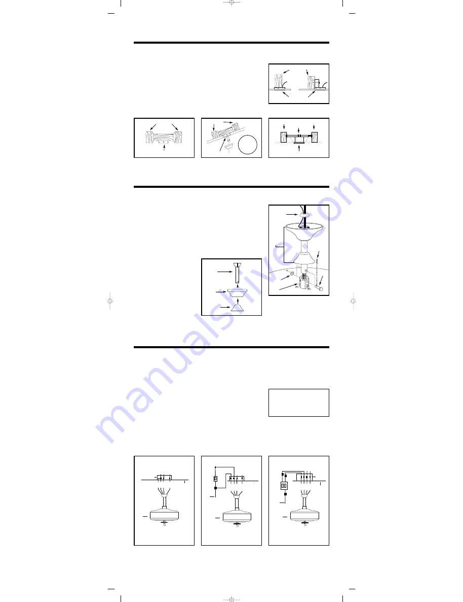
2.
(Fig. 7) Connect the BLACK build-
ing supply wire to the BLACK AND
BLUE fan wires. Connect the WHITE
building neutral wire to the WHITE fan
neutral wire. Connect the COPPER
building ground wire to the GREEN fan
ground wire.
3.
Optional Wall Controls
Wiring connections for optional wall
control are shown in Fig.8 and 9. Figure
9 shows how to wire a fan wall control
switch. This controls the fan only. To
separately control an optional light kit
using the light kit pull chain,you would
have to connect the blue wire from the
fan to the house supply wire, before it
goes to the wall control. This is not an
easy connection, and we suggest you call
a qualified electrician to do it for you.
4.
Inside the ceiling junction box be
sure to spread the wires apart so that the
black and blue connections are on one
side of the outlet box and the white/white
and green/copper connections are on the
other side.
Outlet Box
BLU
BLK
WH
GRN
BLK
WH
Ground
Ceiling
Fan
Fig. 7
Outlet Box
WH
Ground
Fan
Switch
on Wall
BLU
BLK
WH
GRN
BLK
BLU
BLK
BLK
BLK
House
Supply
Wire
Ceiling
Fan
Fig. 8
Outlet Box
Ceiling
Ground
Fan/Light
Switch
on Wall
BLK
BLK
BLK
BLK/WH
BLU
BLU
WH
House
Supply
Wire
WH
BLK
BLU
GRN
Fan
Fig. 9
Use ONLY wall controls approved
by Quorum. Use of unapproved wall
controls will cause unacceptable
humming noise, and voids the fan
warranty.
Set Pin
26° maximum
slope using
4” downrod
Estate Inst -5/04 WET 6/2/2004 11:22 AM Page 3
All manuals and user guides at all-guides.com


