background image


15 

2.4.4.4  Tour 


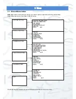
Move the cursor to highlight TOUR item and then click confirm button to go to set interface.  


TOUR NO 

This is to set the tour number. Please use the left/right button on the keyboard or in the speed 

dome terminal menu to set.    


TOUR SETTING: Move the cursor to the TOUR setting item and then click confirm button. You will see the 

following interface:  


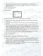
Here you can add or remove the preset, and set the corresponding dwell time and call speed.  


DWELL: This is to set the dwell time. Please use the left/right button on the keyboard or in the speed 

dome terminal menu to set.    


SPEED: Here you can set the speed value. 


When you move the cursor to one tour number, you can use the left/right button to turn the page.  


When you move the cursor to one tour number, please click the confirm button to set the tour. Please use 

up/down button to set preset number, dwell time and speed. Use the left/right button to go to the next tour. Click 

the confirm button to exit the setup. After you completed the setup, move the cursor to back button to go to the 

previous interface. 


DELETE TOUR

This is to delete a tour. Input tour number in TOUR NO and then move the cursor to 

DELETE TOUR, click confirm button to delete. 


CALL: This is to activate tour. Input tour number in tour NO and highlight CALL, click confirm button to 

activate tour.  


STOP: This is to terminate touring. 


BACK: Go back to previous menu.  


EXIT: Log out system menu. 


TOUR   NO


 1 

TOUR SETTING 
DELETE TOUR  
CALL 
STOP 
BACK                     EXIT 
 

NO    PRESET   DWELL       SPEED 
01       000           005                013 
02       000           005                013 
03       000           005                013 


32       000           005                013 

BACK       EXIT 

Summary of Contents for MINI-PTZ-23X-H

Page 1: ...MINI PTZ 23X H 23X ZOOM ANALOGUE PTZ CAMERA User s Manual V1 0 10 2013 ...

Page 2: ...i ...

Page 3: ...de B W Color Mode 2 1 2 12 Auto Focus 2 1 2 13 Backlight Compensation 2 1 2 14 Pan Tilt and Zoom 2 1 2 15 3D Intelligent Location 3 1 2 16 Idle Status 3 1 2 17 Image Stabilizer Flip 3 2 MENU 4 2 1 Screen Menu Index 4 2 2 Self diagnosis System Information 5 2 3 Main Menu 5 2 4 Menu Operation 6 2 4 1 System Information 6 2 4 2 Display Setting 7 2 4 3 Camera Setting 8 2 4 4 Function Setting 12 2 4 5 ...

Page 4: ...iii 3 1 Combination Cable Connection 20 4 FAQ 21 4 1 Daily Maintenance 21 4 2 Problems and Solutions 21 ...

Page 5: ... to be a reference tool for the installation and operation of your system Here you can find information about the corresponding IP camera s features and functions as well as a detailed installation method Before installation and operation please read the following safeguards and warnings carefully ...

Page 6: ...electromagnetic radiation or objects that produce it Please keep sound ventilation around the device at all times Do not allow the water and other liquid to penetrate into the device if casing has been compromised This series product complies with the IP66 standard specified in the Degrees of Protection Provided by Enclosure Please make sure the CCD CMOS component is away from the radiation of the...

Page 7: ...he device Finally use the dry cloth to clean the device 6 About Accessories Always use all the accessories recommended by manufacturer Before installation please open the package and check that all the components are included in the package Contact your local retailer ASAP if something is missing in your package ...

Page 8: ...1 2 Features This PTZ speed dome has the following features 1 2 1 On Screen Menu This series product menu supports multiple languages It is easy for you to view dome information and configure dome camera parameters 1 2 2 Proportional Pan and Tilt This function keeps the image from moving too fast when there is a large amount of zoom The PTZ camera continually decreases or increases pan and tilt sp...

Page 9: ...sition the dome rotates 180 degrees and repositions itself for uninterrupted viewing of any subjects that passes directly beneath the dome 1 2 10 Self diagnosis There is a self diagnosis procedure when camera boots up Tilt and vertical engine check Camera diagnostics 1 2 11 Day Night Mode B W Color Mode Auto manual switches in low illumination Auto camera will automatically adjust CCD light level ...

Page 10: ...ne 1 2 16 Idle Status When there is no available order you can use menu to set dome idle status after specified duration 1 2 17 Image Stabilizer Flip You can enable image stabiliser function and flip in the menu When there is vibration this I S function can guarantee video stability and when it flips you can view the video more clearly ...

Page 11: ...OSITION ZOOM DISP INSIDE TEMP TITILE DISPLAY BACK EXIT DISPLAY SETTING SYSTEM SETTING CAMERA SETTING FUNCTION SETTING EXIT WB SETTING EXPOSURE SETTING DAY NIGHT SETTING FOCUS SETUP ZOOM SPEED APERTURE APERTURE CNT LEVEL NEXT PAGE BACK EXIT PRESET AUTO PAN AUTO SCAN TOUR PATTERN IDLE MOTION NEXT PAGE BACK EXIT ALARM SETTING ALARM NO ACTION PARAMETER CONTACT RELAY OUT RESET DELAY SAVE BACK EXIT SYST...

Page 12: ...ess number H is hard address mode S is software address mode Baud rate Dome communication baud rate Parity Communication parity bit format Software Dome PTZ software version When you are using the control keyboard or the matrix host to control the device please make sure the control parameter of the keyboard or the matrix host is the same with the speed dome OSD including address baud rate parity ...

Page 13: ...u All setups here will not be lost when you encounter a power failure 2 4 1 System Information SYSTEM INFORMATION Move the cursor to SYSTERM INFORMATION and then click the confirm button to go to the third submenu ADDR INFORMATION Move the cursor to SITE INFORMATION and then click confirm button to go to the third submenu SET NORTH Set the camera s benchmark direction so that you can know the angl...

Page 14: ...ou can set address via software It is to say you can use menu to modify dome address The value ranges from 0 to 255 BACK Go back to the previous menu EXIT Log out system menu 2 4 2 Display Setting Move the cursor to DISPLAY SETUP and then click confirm button you can go to the third submenu Please use the left right button on the keyboard or in the speed dome terminal menu to set After completing ...

Page 15: ...ove the cursor to current option and then click confirm button you can go to the third menu DAY NIGHT Set day night mode Move the cursor to current option and then click confirm button you can go to the third menu There are three options auto manual off Please use the left right button on the keyboard or in the speed dome terminal menu to set Please make sure your product supports this function FO...

Page 16: ...mera s terminal menu to set BACK Go back to previous menu EXIT Log out system menu 2 4 3 2 Exposure Setting AE MODE This is where you can set the camera exposure mode This includes auto manual AV iris priority TV shutter priority Please use the left right button on the keyboard or in the speed dome terminal menu to set o Auto This becomes valid after you set the exposure compensation backlight com...

Page 17: ... be noise when the camera is monitoring in low illumination environments You can use the digital filter to process the noise to guarantee the clear video o 3D NOISE REDUCTION This is to set the speed dome 3D noise reduction setup Please use the left right button on the keyboard or in the speed dome terminal menu to set o BLC It is an abbreviation for Back Light Compensation The System can compensa...

Page 18: ...HOLD The speed dome can switch the day night mode when it reached the threshold you set here SAVE This button is for DAY TIME and NIGHT TIME setup After you set the day time or night time you need to move the cursor here and then click confirm button to save current time setup For other setups you do not need to use this button BACK Go back to previous menu EXIT Log out system menu 2 4 3 5 Focus S...

Page 19: ...Y DEFAULT SETTING Move the cursor to current item and then click confirm button to restore factory default setup CAMERA RESTART Move the cursor to current item and then click confirm button to reboot the camera BACK Go back to previous menu EXIT Log out system menu 2 4 4 Function Setting Please go back to main menu and move the cursor to FUNCTION SETTING click confirm button You can see the above ...

Page 20: ...ed to enable display preset title function first Main menu display setting preset title Repeat the above procedures to set more presets When you want to modify a preset you can input the preset number you want to modify and then follow the above steps to set the preset CALL This is to recall a preset Move the cursor to PRESET NO and then input a corresponding preset value Then move the cursor to C...

Page 21: ...e the cursor to the SCAN button and then click confirm button AUTO SCAN NO This is to set the auto scan number Please use the left right button on the keyboard or in the speed dome terminal menu to set SET LEFT LIMIT This is to set the camera left address Click confirm button to save current setup SET RIGHT LIMIT This is to set the camera right address Click confirm button to save current setup SC...

Page 22: ...the left right button to turn the page When you move the cursor to one tour number please click the confirm button to set the tour Please use up down button to set preset number dwell time and speed Use the left right button to go to the next tour Click the confirm button to exit the setup After you completed the setup move the cursor to back button to go to the previous interface DELETE TOUR This...

Page 23: ...ompt you that system has memorised one pattern RUN This is to activate a pattern Input pattern number move the cursor to RUN and click confirm button system begins running pattern STOP This is to stop current pattern Input pattern number move the cursor to STOP and click confirm button System stops current pattern BACK Go back to previous menu EXIT Log out system menu Note The dwell time between t...

Page 24: ...ease move the cursor to the current item and then click the confirm button to go to the next interface PTZ SPEED This is to set the PTZ speed Please use the left right button to set SET ZERO Please move the PTZ to the horizontal coordinates click OK button to confirm POWER UP This is to set the PTZ action when the speed dome boots up Click the confirm button to go to the next interface to set MENU...

Page 25: ...mask setup so that the privacy mask region can move along with the PTZ movement to always cover the object you want to shield PRIVACY NO This is to set the privacy mask zone Please use the left right button on the keyboard or in the speed dome terminal menu to set You can call corresponding privacy mask zone numbers if you have successfully set one up PRIVACY MASKING There are two settings on and ...

Page 26: ...tion once alarm has been triggered There are two alarm signal mode normal open N O and normal closed N C Please use the left right button on the keyboard or in the speed dome terminal menu to set RELAY OUT This is to the set relay alarm mode and reset time There are several options off 1 5S RESET DELAY This is for you to set the alarm reset time Please use the left right button on the keyboard or ...

Page 27: ...ut channels This is to receive relay signal from the external alarm source You can go to dome menu to activate specified preset or pattern When the activation mode is NO Normal Open dome alarms when there is low voltage High voltage will not activate the alarm When the activation mode is NC normal close dome alarms when there is high voltage Low voltage will not activate the alarm Note Dome alarm ...

Page 28: ...e contact retailer to replace power board 2 No self diagnosis occurs Abnormal noises heard coming from camera Power supply is inadequate Replace power supply Mechanical malfunction Seek electrical engineer s help 3 Video signal loss occurs during high speed rotation Power supply is not sufficient Replace power supply 4 Video signal is not successive Circuit connection is loose Reset connection cor...

Page 29: ...For more information about our DVRs and available cameras accessories please visit our website www adata co uk Alternatively scan this QR code with your smart phone to be directed instantly to our website ...

Reviews: