background image

26 

| MENU QUICK REVIEW


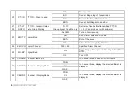
39


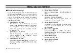
SIG-FC


Bottom Bar Display 
Foreground Color (Text)


Select Color


BLACK, WHITE, RED, BLUE, GREEN, YELLOW, 
INDIGO, PURPLE, GRAY


40


SIG-BC


Bottom Bar Display 
Background Color


Select Color


BLACK, WHITE, RED, BLUE, GREEN, YELLOW, 
INDIGO, PURPLE, GRAY


41


RX-FC


Main LCD Receiving Color 
Foreground Color (Text)


Select Color


BLACK, WHITE, RED, BLUE, GREEN, YELLOW, 
INDIGO, PURPLE, GRAY


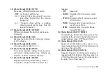
42


TX-FC


Main LCD TX Color 
Foreground Color (Text)


Select Color


BLACK, WHITE, RED, BLUE, GREEN, YELLOW, 
INDIGO, PURPLE, GRAY


43


TXDISP


Transmit Display


POWER


Display Power Level on Bottom Graph


MIC-V


Display Mic Audio Level on Bottom Graph


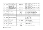
44


MEM-CH


Memorize Channel


000 > 199


Indicates channel number to be stored.


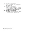
45


DEL-CH


Delete Channel


000 > 199


Indicates channel number to be deleted.


46


SFT-D


Frequency Shift Direction


OFF


No O

set (simplex)


+


Plus frequency shift


-


Minus frequency shift


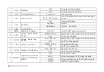
47


OFFSET


Frequency Shift 
O

set Amount


00.00 > 69.99


Frequency shift in MHz


48


ANI


ANI ID Code


Can only be set with software


49


ANI-L


ANI Length


3, 4, 5


Length of ANI ID code


50


REP-S


Repeater Activation Tone


1000Hz, 1450Hz, 1750Hz,


2100Hz


Audible tone for repeater activation


Summary of Contents for KT-8900D

Page 1: ...Mini color screen MobileRadio USER S MANUAL...

Page 2: ......

Page 3: ...ation For vehicles with an air bag do not mount your radio in the area over an air bag or in the air bag deployment area Do not expose the radio to direct sunlight over a long time nor place it close...

Page 4: ...selection 12 Monitor Both VFO MR Modes 13 MENU QUICK REVIEW 14 Quick Menu Settings 14 Menu de nitions 21 PROGRAMMING 28 Frequency Mode vs Channel Mode 28 OTHER SETTINGS 29 Toggle from High to Low Powe...

Page 5: ...ns of damage Carefully open the box and con rm your received the items listed below If you nd the radio or the included accessories are damaged or lost immediately contact yourdealer What s in the Box...

Page 6: ...radio function key Display screen 0 Call key Exit Menu A B C D signal switching alarm function Microphone Connector when in standby press to send caller ID ANI in the selected signaling mode while tr...

Page 7: ...key Microphone Connector when in standby press to send caller ID ANI in the selected signaling mode while transmitting press to send activate signaling press to turn on the squelch repeat to turn off...

Page 8: ...Rear Ports G G TRRS Line Out Includes PTT Microphone Audio out GND 0 DATA Programming Jack Cooling Fan SO 239 RF Antenna Connector Connects to PL 259 Antennas DC Power Input 13 8V 7A Peak G TRRS Line...

Page 9: ...P Higherfrequency DOWN Lower frequency EXIT Exit theAB channel switch alarm function AlarmActivate Long Press SCAN Scanning function 0 LOCK High Low Power Toggle Keyboard Lock Long Press G 0 0 Number...

Page 10: ...G DOWN Lower frequency EXIT Exit the AB channel switch alarm function AlarmActivate Long Press 0 SCAN Scanning function LOCK High Low Power Toggle Keyboard Lock Long Press 0 0 Number 0 1 Number 1 2 Nu...

Page 11: ...annel allowed to TX RX DCS DCS Enabled TX RX or Both Positive O set Freq Mode Channel allowed to RX Only L Transmit Power Low Negative O set Freq Mode Channel allowed to TX Only H Transmit Power High...

Page 12: ...sage editable via PC Programming Current Voltage detected from the power source Numerical scale for microphone transmit audio level intensity Microphone transmit audio level intensity Strength Meter f...

Page 13: ...uency you transmit on it can cause damage with the re ected power going back into the radio Pick an antenna with SWR of less than 1 5 1 to safely transmit Grounding Plane Antennas require an appropria...

Page 14: ...ave Ration can void war ranty support R An Active SWR Meter is a great tool to have when selecting an antenna for your needs You can monitor and confirm that your SWR is within safe levels when settin...

Page 15: ...st FM will stop as soon as an active station is found To enable scanning press and hold the SCAN key for about two seconds Turning the unit ON To turn the unit on simply push and hold the vol ume knob...

Page 16: ...For everyday use Channel MR mode is going to be a whole lot more practical than Frequency VFO mode However Frequency VFO mode is very handy for experimentation out in the eld Frequency VFO mode is al...

Page 17: ...ransmit power set to Low you can use the key to momen tarily switch over to high power if you re having trouble getting through Monitor Both VFO MR Modes You can toggle from VFO and MR Memory Re call...

Page 18: ...equency increments step in VFO mode 2 5kHz 5kHz 6 25kHz 10kHz 12 5kHz 25kHz selectable 2 Enter Menu 2 SQL Sets the receiver squelch level 0 is OFF 1 is the lowest setting through 9 which is the high e...

Page 19: ...ed setting 14 Enter Menu 1 4 DTMFST DTMF transmit tone settings OFF No tones heard through the speaker when transmitting KEY Only manually keyed DTMF codes are heard ANI Only automatically keyed DTMF...

Page 20: ...quelch will open 20 Enter Menu 2 0 PTT ID PTT ID transmit setting OFF no ID code sent when transmitting BOT send ID code at Beginning of Trans mit EOT send ID code at End of Transmit BOTH send ID code...

Page 21: ...y Mode Display C FREQ displaysFrequency CH displays channel number NAME displays assigned channel name 30 Enter Menu 3 0 CD MDF Display Mode Display D FREQ displaysFrequency CH displays channel number...

Page 22: ...39 Enter Menu 3 9 SIG FC Signal Bar LCD Display Foreground Text Col or Color options are BLACK WHITE RED BLUE GREEN YELLOW INDIGO PURPLE GRAY 40 Enter Menu 4 0 SIG BC Signal Bar LCD Display Background...

Page 23: ...z 51 Enter Menu 5 1 REP M Repeater forwarding mode setting Used in conjunction with two radios connected as a repeater OFF turned o CARRI forwards after it receives a carrier call CTDCS forwards after...

Page 24: ...time use with Menu 46 56 Enter Menu 5 6 DTMF G Adjust the gain of the DTMF tones Selectable from 0 60 0 being the quietest level and 60 being the loudest modulated DTMF tones 57 Enter Menu 5 7 RESET...

Page 25: ...nels to allow dual tri and quad watch Selected Memory Displays A B C D M Selected Memory A DisplayA B Display B C Display C D Display D M B M C M D M A B M A C M A D M B C M B D M C D M A B C M A B D...

Page 26: ...gital Coded Squelch D023N D754I Squelch opens when proper DCS code is detected OFF No DCS code required 11 R CTCS Receive Analog Tone Squelch 67 0 254 1Hz Squelch opens when proper CTCSS tone detected...

Page 27: ...ve CO Carrier Operation Scan stops when signal detected Scan resumes when signal disappears SE Search Operation Scan stops when signal detected Scanning will not resume 18 OPTSIG Optional Signaling OF...

Page 28: ...TP Alarm Mode ALARM Turn on Alarm sound ANI Send Alarm code and ID code BOTH Both of the above OFF Alarm Mode Completely Disabled 24 EMC CH Alarm Channel 000 199 Speci ed Alarm Channel 25 SIG BP Sign...

Page 29: ...olor BLACK WHITE RED BLUE GREEN YELLOW INDIGO PURPLE GRAY 34 MAINBC MAIN LCD Display Background Color Select Color BLACK WHITE RED BLUE GREEN YELLOW INDIGO PURPLE GRAY 35 MENUFC On Screen Menu Foregro...

Page 30: ...N YELLOW INDIGO PURPLE GRAY 43 TXDISP Transmit Display POWER Display Power Level on Bottom Graph MIC V Display Mic Audio Level on Bottom Graph 44 MEM CH Memorize Channel 000 199 Indicates channel numb...

Page 31: ...Primary Channel 1 50 seconds This is the delay time before returning to the primary channel after secondary signal is clear 53 STE Squelch Tail Elimination Requires both radios have function ON OFF F...

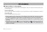
Page 32: ...annels 28 PROGRAMMING PROGRAMMING R All programming must be initially done in the frequency mode VFO only From there you have the option of assigning the entered data to a specific channel for access...

Page 33: ...standby to turn on o the keypad lock out function The Lock icon appears when the radio is locked out PTT ID Setting 1 Use PC software to change PTT ID code 2 Set the Menu 18 settings on the radio to...

Page 34: ...ved calling list requires the PC software to the one of the 15 Memory call banks in the radio To transmit select the Pre set DTMF saved setting on Menu 22 and then press the call key to send the saved...

Page 35: ...itself the radio is set to receive command tones if the Monitor Remote Kill tone is received the radio will revived from a stun kill command Both the master ID station and remote stun signal must be s...

Page 36: ...f operation Time carrier or search each of w hich is explained in further details in their respec tive section below Setting scanner mode 1 Press the MENU key to enter the menu 2 Enter 17 on your nume...

Page 37: ...ncy stability 2 5ppm Frequency step kHz 2 5K 5 0K 6 25K 10 0K 12 5K 25 0K Squelch Setup CARRIER CTCSS DCS 5Tone 2TONE DTMF Antenna impedance 50 Ohm Operating temperature 20 C to 60 C Supply voltage 13...

Page 38: ...0dB Audio response 1 3dB 0 3 3KHz 1 3dB 0 3 2 55KHz Signal to noise ratio 45dB 40dB Audio Distortion 5 Audio output power 2W 10 TRANSMIT Broadband Wide band Output power 15W 5W Modulation Mode 16K F3E...

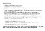
Page 39: ...uses and can radiate radio frequency energy and if not installed and used in accordance with the instructions may cause harmful interference to radio communications However there is no guarantee that...

Page 40: ...emiconductor etc not authorized by the FCC equipment authorization for this radio could violate FCC rules Note Use of this radio outside the country where it was intended to be distributed is subject...

Page 41: ...Mini color screen MobileRadio...

Reviews: