R. Lang Company
Date: 05/01/2019
Tel: 800-677-5264 | Fax: 888-526-4329
Installation
Page 2 of 5
Over tensioning the spring
can destroy it and void the
product warranty.
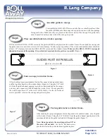
Locate the guide locks (R4060 and R4070) and install them in the guides (R2040),
insuring they are seated all the way to the bottom
fl
ange. The magnet goes to the outside
of your building (Figure 3).
Trim the Mesh Lock
TM
at the magnets.
Step 2
Figure 3
Step 3
Test & Pretension the screen for operation.
The ROLL
AWAY
®
window screen was shipped with a minimal amount of tension on the
screen. Test the tension on the screen by holding the canopy horizontally, withdrawing the
screen from the canopy, and allowing it to retract, taking care to keep the screen within
Figure 1
CAUTION!
the canopy end cap guide runners. If the screen
does not fully retract, add tension to the spring
by engaging the tension adjustment screw
with a #2 Phillips bit and turning the tension
adjustment screw counterclockwise. It will
require 30 turns of the tension adjustment screw
to add one turn of tension to the spring. Add just
enough tension to keep the drawbar against the
canopy as shown in Figure 1.
Do not push the adjustment screw.
Use
fi
rm
pressure when adjusting the tension.
Install guide locks in guides.
Locate the guides (R2040) Note that the Mesh Lock
TM
has long brushes and short brushes. The long brushes go to the outside of
your building (Figure 2). Mesh Lock
TM
is crimped in place to avoid movement. If Mesh Lock
TM
slides out of the channel, re-position
in the channel and crimp (squeeze) the end with pliers to secure in place before guides are installed.
Crimp
Locations
Figure 2
OUTSIDE
Step 4
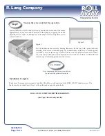
If the guide locks are installed correctly, the Mesh Lock
TM
long brushes cover
the magnets in the guide locks. To insure proper operation of the magnetic
latch, the long brush must be trimmed away at the magnet. Using a utility
knife or scissors, cut the long brush away for a distance of 1 inch, from the
bottom of the guide (Figure 4). Repeat for both guides.
Figure 4
NOTE: Counterclockwise adjustment will increase spring tension.


