Page 2
05103V-90(J)
connected to the anti-static mounting post. This terminal should
be connected to an earth ground (Refer to wiring diagram). Initial
installation is most easily done with two people; one to adjust
the instrument position and the other to observe the indicating
device. After initial installation, the instrument can be removed
and returned to its mounting without re-aligning the vane since the
orientation ring preserves the wind direction reference. Install the
Wind Monitor following these steps:
1. MOUNT WIND MONITOR
a) Place orientation ring on mounting post. Do Not tighten
band clamp yet. Orientation ring may be omitted when
portable tripod is used.
b) Place Wind Monitor on mounting post. Do Not tighten band
clamp yet.
2. CONNECT SENSOR CABLE.
a) Refer to wiring diagram located at back of manual.
3. ALIGN VANE
a) Connect instrument to indicator.
b) Choose a known wind direction reference point on the
horizon.
c) Sighting down instrument centerline, point nose cone at
reference point on horizon.
d) While holding vane in position, slowly turn base until
indicator shows proper value.
e) Tighten mounting post band clamp.
f) Engage orientation ring indexing pin in notch at instrument
base.
g) Tighten orientation ring band clamp.
CALIBRATION
The Wind Monitor is fully calibrated before shipment and should
require no adjustments. Recalibration may be necessary after
some maintenance operations. Periodic calibration checks are
desirable and may be necessary where the instrument is used in
programs which require auditing of sensor performance.
Accurate wind direction calibration requires a Model 18112 Vane
Angle Bench Stand. Begin by connecting the instrument to a signal
conditioning circuit which has some method of indicating a wind
direction value. This may be a display which shows wind direction
values in angular degrees or simply a voltmeter monitoring the
output. Orient the base so the junction box faces due south.
Visually align the vane with the crossmarkings and observe the
indicator output. If the vane position and indicator do not agree
within 5°, it may be necessary to adjust the potentiometer coupling
inside the main housing. Details for making this adjustment appear
in the MAINTENANCE, POTENTIOMETER REPLACEMENT,
outline, step 7.
It is important to note that, while the sensor mechanically rotates
through 360°, the full scale wind direction signal from the signal
conditioning occurs at 355°. The signal conditioning electronics
must be adjusted accordingly. For example, in a circuit where 0
to 5.000 VDC represents 0° to 360°, the output must be adjusted
for 4.930 VDC when the instrument is at 355°. (355°/360° X 5.000
volts = 4.930 volts).
Wind speed calibration is determined by propeller pitch and the
output characteristics of the transducer. The calibration formula
relating propeller rpm to wind speed is shown below. Standard
accuracy is ±0.3 m/s (0.6 mph). For greater accuracy, the sensor
must be individually calibrated in comparison with a wind speed
standard. Contact the factory or your supplier to schedule a NIST
(National Institute of Standards & Technology) traceable wind
tunnel calibration in our facility.
To calibrate wind system electronics, temporarily remove
the propeller and connect an Anemometer Drive (18802 or
equivalent) to the propeller shaft. Apply the calibration formula to
the calibrating motor rpm and adjust the electronics for the proper
value. For example, with the propeller shaft turning at 3600 rpm,
adjust an indicator to display 17.6 m/s [3600 rpm x .0049 (m/s)/rpm
= 17.6 m/s].
Details on checking bearing torque, which affects wind speed and
direction threshold, appear in the following section.
CALIBRATION FORMULAS
Model 05103V Wind Monitor w / 08234 Propeller
WIND SPEED vs PROPELLER RPM
m/s
=
0.00490 x rpm
knots
=
0.00952 x rpm
mph
=
0.01096 x rpm
km/h
=
0.01764 x rpm
WIND SPEED vs 0-5 VDC OUTPUT
m/s
=
mV x 0.0200
knots
=
mV x 0.0389
mph
=
mV x 0.0447
km/h
=
mV x 0.0720
WIND DIRECTION vs 0-5 VDC OUTPUT
DEGREES
= mV x 0.072
MAINTENANCE
Given proper care, the Wind Monitor should provide years of
service. The only components likely to need replacement due to
normal wear are the precision ball bearings and the wind direction
potentiometer. Only a qualified instrument technician should
perform the replacement. If service facilities are not available,
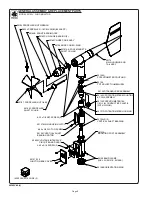
return the instrument to the company. Refer to the drawings to
become familiar with part names and locations. The asterisk
* which appears in the following outlines is a reminder that
maximum torque on all set screws is 80 oz-in.
POTENTIOMETER REPLACEMENT
The potentiometer has a life expectancy of fifty million revolutions.
As it becomes worn, the element may begin to produce noisy
signals or become non-linear. When signal noise or non-linearity
becomes unacceptable, replace the potentiometer. Refer to
exploded view drawing and proceed as follows:
1. REMOVE MAIN HOUSING
a) Unscrew nose cone from main housing. Set o-ring aside for
later use.
b) Gently push main housing latch.
c) While pushing latch, lift main housing up and remove it from
vertical shaft bearing rotor.
2. UNSOLDER TRANSDUCER WIRE
a) Remove junction box cover, exposing circuit board.
b) Remove screws holding circuit board.
c) Unsolder three potentiometer wires (white, green, black),
two wind speed coil wires (red, black), and earth ground wire
(red) from board.
3. REMOVE POTENTIOMETER
a) Loosen set screw on potentiometer coupling and remove
it from potentiometer adjust thumbwheel.
b) Loosen set screw on potentiometer adjust thumbwheel
and remove it from potentiometer shaft.


