

Page 1
32500-90(N)
MODEL 32500
ELECTRONIC COMPASS
WITH SERIAL INTERFACE
SPECIFICATIONS
*
Compass:
Resolution:
0.5
degrees
Accuracy:
±2 degrees (rms)
Wind Speed Input:
Sensor Type:
AC Frequency Generator
Sensitivity:
50mV p-p at 10Hz
Range:
0-2000
Hz
Wind Direction Input:
Sensor
Type:
Potentiometer
Range:
0-5000mV = 0 to 355 degrees
Excitation:
5000mV (limited to 5 mA)
Voltage Inputs (Auxiliary Sensor Inputs):
Resolution:
12-bit
VIN1 and VIN2
0-1000mV
VIN3 and VIN4
0-5000mV
Voltage Outputs:
OUT1
0-5000mV
0-100 m/s wind speed
OUT2
0-5000mV
0-360° true wind
direction
Serial Output:
Full duplex RS-232,
Half duplex RS-485 (2 mS turnaround)
1200, 4800, 9600, 19.2K, & 38.4K baud
8 data, 1 stop, no parity
Operating Temp:
-50°C to 50°C
Power:
11 to 30 VDC, 40 mA
Mounting:
1 inch IPS (1.34 inch actual diameter)
Size:
4.75” (12cm) H
0.87” (7.3cm) W
2.12” (5.3cm) D
*
Specifi cations subject to change
1.0 INTRODUCTION
The Model 32500 ELECTRONIC COMPASS measures magnetic
heading, wind speed and direction signals from YOUNG sensors, and
signals from four general purpose voltage inputs. Wind direction input
may be combined with compass measurements to obtain true direc-
tion. Voltage inputs may be used with YOUNG temperature, humidity,
barometric pressure, and other sensors. One voltage input may be
confi gured for connection to a tipping bucket precipitation gauge.
Measurements are available in several serial data formats in either full
duplex RS-232 or half-duplex RS-485 signals. Both continuous and
polled serial outputs are available. When polled, up to 16 units can
be networked together. For marine applications the 32500 produces
standard NMEA serial output sentences. Calibrated voltage outputs
for wind speed and direction are also provided when the 32500 is con-
nected to a YOUNG wind sensor.
2.0 INSTALLATION
The 32500 is supplied in a weather-resistant enclosure with a mount-
ing adapter that fi ts 1 inch IPS pipe (1.34 inch nominal diameter).
When used with the YOUNG Wind Monitor, the mounting adapter
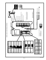
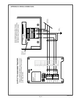
engages the Wind Monitor orientation notch. Refer to the WIRING
DIAGRAM for electrical connection details and jumper settings.
It is important to install the 32500 so it remains level during opera-
tion. This becomes increasingly inportant when used at northern and
southern latitudes far from the equator since progressively more of the
earth’s magnetic fl ux becomes vertical. By keeping the 32500 level at
these latitudes, the measurements will be free of the vertical fl ux infl u-
ence and remain accurate.
If possible, avoid installing the compass near magnetic devices or
machinery. After installation, the compass must be calibrated to cor-
rect for local magnetic conditions. If the compass is moved or its local
environment changes signifi cantly (machinery moved), the compass
should be calibrated again.
3.0 OPERATION
Operation begins automatically when power is applied. Jumpers con-
fi gure the 32500 for common output formats.
3.1 COMPASS CALIBRATION
When the 32500 is operated for the fi rst time, its internal compass
must be calibrated for local conditions. To calibrate the compass,
please follow the steps outlined below.
1. Remove cover from compass. Press and hold CALIBRATE button
for 5 seconds. The CALIBRATE indicator will begin to blink. Refer
to WIRING DIAGRAM to locate CALIBRATE button.
2. Slowly rotate vehicle on which compass is mounted. Steer vehicle
in a tight circle and make TWO complete revolutions. Each revolu-
tion should take at least one minute. THE COMPASS MUST
REMAIN LEVEL DURING CALIBRATION.
3. After two complete revolutions, press and hold CALIBRATE button
until indicator stops blinking. Calibration is now complete. Calibra-
tion parameters are retained when power is removed.
4. Replace cover. Use this procedure to recalibrate compass at any
time.
Serial communication command may also be sent to start and stop the
compass calibration. Please see section 4.2 SERIAL COMMANDS for
details.
3.2 SIGNAL INPUTS
The 32500 has two special wind speed and direction inputs for
YOUNG sensors and four voltage input channels for connection to
other meteorological instruments like temperature, humidity, and
barometric pressure sensors. Two of the voltage input channels may
also be confi gured as alternative wind speed and wind direction in-
puts for sensors like the Young 85XXX family. For best performance,
sensors should be installed within 3m (10ft.) of the 32500.
Measurements from the voltage input channels are converted to
numerical values (0-4000) and sent in the serial ASCII output string:
VIN1 and VIN2 full scale input is 1000mV DC, therefore:
Input millivolts = Serial output value / 4
VIN3 and VIN4 full scale input is 5000mV, therefore:
Input millivolts = Serial output value x 1.25
VIN3 and VIN4 may be confi gured as alternative wind speed and
direction inputs using CMD250 in SOFTWARE mode. Please see
section 4.2 SERIAL COMMANDS.
Selecting PRECIP or PRECIP POLLED output formats will confi gure
VIN4 to count tips from a tipping bucket precipitation gauge.
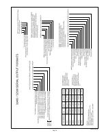
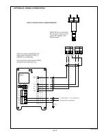
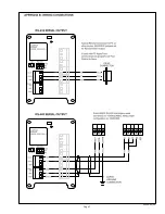
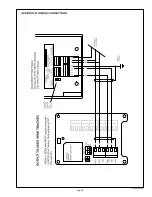
Please refer to SERIAL FORMAT DIAGRAM and WIRING DIAGRAM
in the Appendix for additional details.
Summary of Contents for 32500
Page 5: ...Page 4 32500 90 N...
Page 6: ...Page 5 32500 90 N...
Page 7: ...Page 6 32500 90 N...
Page 8: ...Page 7 32500 90 N...
Page 9: ...Page 8 32500 90 N...
Page 10: ...Page 9 32500 90 N...


