background image

 8


Electrical installation cont.


Input Connections


Make sure the voltage, phase and frequency of input power is as specified on machine rating 

plate located at rear of machine.


Have a qualified electrician provide suitable input power as per national electrical codes. Make 

sure machine is earthed / grounded.


Make sure fuse or circuit breaker is correct rating for machine. Using fuses or circuit breakers 

smaller than recommended will result in 

nuisance

’ 

shut off from welder inrush currents even if 

welding at low amperages.


Failure to follow these instructions can cause immediate failure within the welder and void ma-

chines warranty.


Turn the input power OFF at the mains switch & fuse box before working on this equipment. Have 

a qualified electrician install & service this equipment.


Allow machine to sit for 5 minutes minimum to allow the power capacitors to discharge before 

working inside this equipment. Do not touch electrically live parts


The TIG171

-

TFT DIGITAL Inverter Tig Welder requires a 240V 50/60Hz supply. It requires a 16A 

supply. It comes with a 2.5 metre mains cable attached.


Connect wires according to national coding. 

Brown wire –


Live


Blue wire –


Neutral


Green/Yellow Wire –


Earth (Ground)


Connecting to an Engine Driven Generator


If connecting this machine to an engine driven generator please ensure the following


Minimum Generator KVA Output –


6

KVA continuous Generator to be fitted with AVR 

(automatic voltage regulation) DO NOT USE ON A GENERATOR WITHOUT AVR


Connecting to a generator without the above minimum requirements will in

-

 validate your war-

ranty.


Summary of Contents for TIG171 TFT

Page 1: ...www r techwelding co uk email salesdept r techwelding co uk Tel 01452 733933 Fax 01452 733939 R TECH TIG171 TFT DIGITAL AC DC TIG WELDER OPERATION INSTRUCTIONS Version 2023 11...

Page 2: ...2...

Page 3: ...ns 8 Connections 11 Controls Settings 14 AC TIG EASY SETUP 16 DC TIG EASY SETUP 21 DC TIG Manual Mode 26 AC TIG Manual Mode 36 AC Amplitude 46 Memory Storing 47 MMA STICK EASY SETUP 48 MMA STICK Manua...

Page 4: ...ms for material damaged in shipment must be made by purchaser against the transportation company used Please record your equipment identification below for future reference This information can be fou...

Page 5: ...gas 5 AC Waveforms Square Soft Square Triangular Sine Sine T and Trapezoidal wave forms Giving the ultimate control of weld pool and bead AC Frequency to 20 400Hz Increased arc focus 3 Start modes HF...

Page 6: ...here clean cooling air can freely circulate in and out of the front rear louvre vents Dirt dust or any foreign material that can be drawn through vents into welder must be kept to a mini mum Failure t...

Page 7: ...ed interference can develop in the following ways 1 Direct interference from welder power source 2 Direct interference from the welding leads 3 Direct interference radiated from feedback into power li...

Page 8: ...box before working on this equipment Have a qualified electrician install service this equipment Allow machine to sit for 5 minutes minimum to allow the power capacitors to discharge before working in...

Page 9: ...ual Pre flow gas 0 60 seconds Up slope time 0 30 seconds Start amps 2A DC 3A AC to 170A Down slope time 0 60 seconds End amps 2A DC 3A AC to 170A Post flow gas time 0 60 seconds DC Pulse amps 3 100 DC...

Page 10: ...ess programs 1 1 2 1 5 2 3 4 5mm Joint type programs Tee Lap Butt Corner Edge Pulse level programs 05Hz 1Hz 2Hz 50Hz 200Hz Pulse amps 75 Pulse Width 50 AC Frequency 100 Hz AC balance 25 35 Trigger typ...

Page 11: ...me 0 2 seconds Hot start 0 100 Arc Force 0 100 Cellulosic Rods YES V R D Voltage reduction YES Remote amp function YES Fan on demand TIG MMA ON Mode1 Temperature control Mode2 1 minute timer on arc ig...

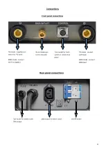
Page 12: ...MMA mode connect earth to negative Quick release gas torch connector 7 pin socket for torch switch or remote foot pedal TIG mode connect earth lead MMA mode connect MMA lead Rear panel connections Fu...

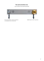
Page 13: ...13 Rear panel connections cont Gas connector Extra earth connection 3 8 BSP male connector for gas input Extra earth connection used if you experience local interference not normally used...

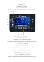
Page 14: ...Control knob Turn to change setting in small amounts press and turn to change in larger steps 4 LED indicator for weld mode selected 5 Left arrow button use to scroll left in menus 6 SAVE LOAD button...

Page 15: ...all weld settings before beginning to weld on manual welders we have done this for you You simply select the following from easy to understand screen Tungsten size Material thickness Filler rod mater...

Page 16: ...Then use control knob to select value required In image below you can see TUNSGTEN SIZE is shown at bottom of screen and circle is highlighted in RED and showing 2 4mm size selected Once correct tungs...

Page 17: ...ALMG 5356 Filler Rod ALSI 4043A Filler Rod Once correct material work thickness has been selected press right arrow to move to next setting JOINT TYPE Select from 5 joint types as below Once correct m...

Page 18: ...80A then base amps will be 60A At 0 5Hz the machine will switch between main amps selected and base amps every half a second At 50Hz the machine will switch between main and base amps 50 times a secon...

Page 19: ...ress foot pedal to start weld fully depress pedal to get 100 of amps shown in recommended settings I E If recommended setting was 120A on a full depress of pedal you will get 120A if pedal only presse...

Page 20: ...ize If not to hand you can use a larger size You are now ready to weld Press trigger or foot pedal to weld If you want to change any settings just simply use left right arrows to highlight setting in...

Page 21: ...uired In image below you can see TUNSGTEN SIZE is shown at bottom of screen and circle is highlighted in RED and showing 2 4mm size selected MATERIAL THICKNESS Then use control knob to select work thi...

Page 22: ...being welded STEEL Mild Steel SS Stainless Steel Once correct metal type has been selected press right arrow to move to next setting JOINT TYPE Select from 5 joint types as below Once correct joint ty...

Page 23: ...s is 80A then base amps will be 60A At 0 5Hz the machine will switch between main amps selected and base amps every half a second At 50Hz the machine will switch between main and base amps 50 times a...

Page 24: ...ress foot pedal to start weld fully depress pedal to get 100 of amps shown in recommended settings I E If recommended setting was 120A on a full depress of pedal you will get 120A if pedal only presse...

Page 25: ...ic size If not to hand you can use a larger size You are now ready to weld Press trigger or foot pedal to weld If you want to change any settings just simply use left right arrows to highlight setting...

Page 26: ...is menu press the arrow button to highlight in red setting to be changed then use control knob to select desired setting HF Options HF start normal auto arc starting LIFT Lift start for welding withou...

Page 27: ...y you will get 60A 4T F Torch trigger latch operation same as 4T but with amperage control by slider rotary knob on torch handle 2T F Torch trigger operation for on off with amperage control by slider...

Page 28: ...nd level screen will show as below Pre flow Gas Use control knob to adjust required Pre flow gas time then press arrow button to move to next setting Adjustable between 0 0 60 seconds Start amps Use c...

Page 29: ...ust Up slope time then press arrow button to move to next setting Adjustable between 0 0 30 seconds Down slope Use control knob to adjust Downslope time then press arrow button to move to next setting...

Page 30: ...ost flow gas time Use control knob to adjust post flow gas time then press arrow button to move to next setting Adjustable between 0 0 60 seconds Once all settings have been set you can start welding...

Page 31: ...ns in DC manual 2nd screen Pulse Time Use control knob to adjust required pulse time then press arrow button to move to next setting Adjustable between 5 95 Pulse Frequency Use control knob to adjust...

Page 32: ...lse or base At a low the base current will be on longer so you will reduce heat input At a high the peak current will be on longer so you increase heat input Pulse Frequency This adjusts how often the...

Page 33: ...first tack and then another tack weld will be started and this will be repeated for as long as trigger is pressed Pre flow Gas Use control knob to adjust required pre flow gas then press arrow button...

Page 34: ...stitch time of 0 0s is selected then only one tack will happen on trigger press once stitch time is above 0 0s then after first tack you will have this delay time and then another weld will be produce...

Page 35: ...pressed You can also set a stitch time which will then set a delay time after first spot and then another spot weld will be started and this will be repeated for as long as trigger is pressed This is...

Page 36: ...OME SCREEN The above image shows the home page for AC manual mode From this menu press the arrow button to highlight in red setting to be changed then use control knob to select desired setting HF Opt...

Page 37: ...get 120A if pedal only pressed halfway you will get 60A 4T F Torch trigger latch operation same as 4T but with amperage control by slider rotary knob on torch handle 2T F Torch trigger operation for...

Page 38: ...d level screen will show as below Pre flow Gas Use control knob to adjust required Pre flow gas time then press arrow button to move to next setting Adjustable between 0 0 60 seconds Start amps Use co...

Page 39: ...row button to move to next setting Adjustable between 0 0 60 seconds Waveform AC Use control knob to select AC waveform required then press arrow button to move to next setting AC Wave modes available...

Page 40: ...knob to adjust AC Frequency then press arrow button to move to next setting Adjustable between 20Hz 400Hz AC Balance Use control knob to adjust AC balance then press arrow button to move to next sett...

Page 41: ...ob to adjust Downslope time then press arrow button to move to next setting Adjustable between 0 0 60 seconds End amps Use control knob to adjust end amps then press arrow button to move to next setti...

Page 42: ...ime then press arrow button to move to next setting Adjustable between 0 0 60 seconds Once all settings have been set you can start welding immediately or return to home screen by pressing home button...

Page 43: ...ions in AC manual 2nd screen Pulse Time Use control knob to adjust required pulse time then press arrow button to move to next setting Adjustable between 5 95 Pulse Frequency Use control knob to adjus...

Page 44: ...lse or base At a low the base current will be on longer so you will reduce heat input At a high the peak current will be on longer so you increase heat input Pulse Frequency This adjusts how often the...

Page 45: ...PULSE After selecting ADVANCED PULSE ON in home screen you will now see 1 changed option in AC manual 2nd screen DC AMPS DC AMPS Use control knob to adjust required DC Amps then press arrow button to...

Page 46: ...lowing narrower welds and use of a smaller tungsten A good example is welding thicker aluminium you can enter a high EN amps and a much lower EP into the tungsten This will provide faster travel speed...

Page 47: ...rogram save menu press the SAVE LOAD button the following screen will appear Use the arrow buttons to move to required save slot Now press and hold the SAVE button for 3 seconds the saved program will...

Page 48: ...efore beginning to weld on manual welders we have done this for you You simply select the following from easy to understand screen Electrode type Electrode size Material thickness Material type Weldin...

Page 49: ...n middle of display You can trim this amperage using control knob 10 amps to suit you personal preference of travel speed weld bead characteristics 1 ELECTRODE TYPE DC 6010 6011 6013 7018 308 309 316...

Page 50: ...ON When switched on the machine will use inbuilt technology to stop electrode from sticking to material REMOTE OFF ON When switched on you can control the amperage remotely by foot pedal or other remo...

Page 51: ...red then turn control knob to adjust Hot Start This controls the extra amount of amperage at beginning of weld to help stop rod sticking Adjustable from 0 100 Hot Start Time This controls how long the...

Page 52: ...arameters User arrow buttons to highlight setting in red then turn control knob to adjust AC Frequency Hz Use control knob to adjust AC Frequency then press arrow button to move to next setting Adjust...

Page 53: ...lso gives a quieter working environment especially when working on thin material so only using low amperage power MODE2 Fan on arc ignition The machine will start the fan as soon as an arc has been es...

Page 54: ...ned on once arc is struck The machine will start the water cooler as soon as an arc has been established it will continue to run for 1 minute after you have finished welding To access water cooler men...

Page 55: ...ns E02 Overcurrent Reset machine and if problem persists contact R Tech support team E05 Shorted Trigger This will show after the torch trigger or foot pedal has been pressed and the arc has not been...

Page 56: ...56...

Page 57: ...57...

Reviews: