background image


12

5. 

Gas post flow adjustment


Adjustable from 1 – 10 seconds. The gas keeps flowing after weld has finished, this cools & 
stops tungsten from getting contaminated. Note: Gas pre-flow time is fixed at 0.5 seconds 
in TIG mode but no pre-flow time will occur if the arc is restarted during post flow time as 
gas is already flowing. 
 

6. 

MMA-TIG mode switch. 


Switches between TIG (GTAW) & MMA STICK (SMAW) welding. 
 

7. 

Pulse On/Off switch 
 

This turns the pulse welding on and off. 


8. 

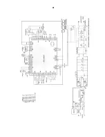
2/4 Way selector switch


2/4 Step trigger mode switch – tig welding can either be done in 2 or 4 step mode. 
 
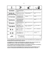
When the trigger mode is in the 2 step position the following sequence will occur 


Press and hold the Tig torch switch to start sequence. 

 
The machine will open gas valve to start flow of shield gas, after a 0.5 seconds pre-flow 
time to purge air from torch hose the welding output of machine will be turned on and the 
arc will be started. After the arc is started the output current will increase from the start 
(min) current to base (main) current in time selected by slope-up. 
 
Release the Tig torch switch to end sequence. 
 
The machine will now decrease output to finish (min) current in time set by slope-down, 
once at finish (min) current the machine will stop output and the gas valve will continue to 
operate for the selected time (post flow) 
 
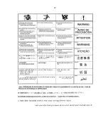
Possible variations of this standard sequence are shown in diagram below. It is possible to 
press and hold tig torch switch a second time during down slope time to restart. After the 
switch is pressed the output current will raise to base (main) current 


Summary of Contents for TIG180PDC

Page 1: ...www r techwelding co uk email sales r techwelding co uk Tel 01452 733933 Fax 01452 733939 TIG180PDC TIG WELDER OPERATION INSTRUCTIONS...

Page 2: ...2...

Page 3: ...chine Product TIG180PDC Serial No ___________________________________ Date of Purchase _____________________________ Where Purchased _____________________________ Whenever you request replacement part...

Page 4: ...e output ratings and duty cycle as per machine specifications with thermostat protection of the output coils and rectifiers Welding Capability Duty Cycle The R Tech Tig180PDC is rated at 180 Amps at 6...

Page 5: ...articles towards the welder An abundance of conductive material can cause plant failure Stacking This machine cannot be stacked Transport Unloading Never underestimate the weight of equipment never mo...

Page 6: ...these contributing factors in mind installing equipment as per following instructions should minimize problems 1 Keep the welder input power lines as short as possible and enclose as much of them as...

Page 7: ...trically live parts The TIG180PDC Inverter Tig Welder requires a 240V 50 60Hz supply It requires a 16A supply for Tig operation and a 22A supply for MMA welding It comes with a 3 metre mains cable att...

Page 8: ...sis If experiencing localized interference when using machine connect workbench to this point using correct graded earth wire not normally used 3 Gas input connector Connect input gas hose ensuring co...

Page 9: ...mp to work bench 4 Torch control socket 7 Pin Connect torch control plug To avoid a High Frequency shock keep the Tig torch in good condition and replace if any of the insulation is damaged Connect th...

Page 10: ...Welding Fig 3 1 Negative power connector Connect the earth lead to by inserting and twisting until tight and the earth clamp to work bench 2 Positive power connector Connect the electrode holder by i...

Page 11: ...2 Down slope Down Slope adjustment 0 5 seconds The main welding current decreases from main amperage to minimum amperage in time selected when weld finished 3 Main current control This adjusts the ma...

Page 12: ...switch to start sequence The machine will open gas valve to start flow of shield gas after a 0 5 seconds pre flow time to purge air from torch hose the welding output of machine will be turned on and...

Page 13: ...nt will be at start min current This condition can be maintained as long as required Release the tig torch switch to go to step 2 The machine will now increase output to base main current in time set...

Page 14: ...n be dangerous Keep your head out of fumes gases produced from welding Use ventilation or exhaust to remove fumes gases from breathing zone and general area WARNING WELDING SPARKS can cause fire or ex...

Page 15: ...in fewer deformations and reduced chance of cracking There are no set rules for pulse welding as this is down to personal choice by the welder Welding in TIG mode with Remote foot pedal 1 Connect the...

Page 16: ...250 4 0mm 5 32 380 500 240 220 320 4 8mm 3 16 500 750 300 280 390 6 4mm 1 4 750 1000 400 360 525 Welding in STICK MMA SMAW Mode 1 Fit MMA electrode holder to machine 2 Fit earth lead to machine and t...

Page 17: ...orch and cables in good condition 4 Clean air vents to ensure proper air flow and cooling 5 The fan motor has sealed bearings which requires no maintenance Troubleshooting Service repair should only b...

Page 18: ...tput Power light is lit Gas at torch end when trigger pressed Check torch condition possible break in torch power cable replace torch Machine keeps overheating Warning light is lit on machine Check if...

Page 19: ...gas hoses Black areas along weld bead 1 Clean any oily or organic contamination from the work piece 2 Tungsten electrode contaminated Replace or sharpen 3 Check for leaks or contamination on gas hoses...

Page 20: ...ing current set to high reduce amperage or use thicker electrode Contaminated electrodes or material Electrode sticks in weld puddle Welding current is set too low Arc is too short keep electrode furt...

Page 21: ...21 21...

Page 22: ...22...

Page 23: ...23...

Page 24: ...24...

Reviews: