12
/ 30
User Manual
Rev. 1.0 - 18/06/12
DTUTT1K2HP1D
ELETTRONICA
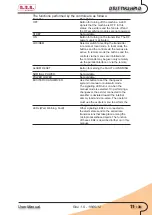
6.2.3 Analogue instruments
The control unit of
DTUTT1K2HP1D
contains an analog meter with a rotating
selector that are useful for an immediate display of the following parameters:
Function
Description
FWD PWR
Transmitter direct power
RFL PWR
Transmitter reflected power
UNBAL
Transmitter unbalancing power
PWR EXC1
Power supplied by the exciter currently
connected to the amplifier. This value is
measured by the machine in the splitter
section
PWR EXC2
Power supplied by the exciter currently
connected to the internal load. This value
is measured by the amplifier in the splitter
section
EXT FWD PWR
Direct power of an external combiner.
EXT RFL FWD
Reflected power of an external combiner.
EXT UNBAL
Unbalancing power of an external combiner.
These three values are used when the
transmitter is connected to a 1+1 system.
The SET outputs may also be connected to
these quantities.
6.3 First Start
This section describes the procedure for powering-on the machine the first time. For
simplicity’s sake, the automatic control capacities of the exciters are temporarily disabled.
Refer to chapter 5.4 that provides the instructions for turning on the
DTUTT1K2HP1D
in the various cases.
6.3.1 Preliminary operation
Before activating this piece of equipment, the necessary connections must be
performed, and in particular:
• Power supply
• Modulating signals (TV, Audio or MPX, RDS...)
• RF load (antenna feeder or dummy load)
About to the connections of the power supply and the modulating signals, please
refer to chapter 5.1.
The machine’s RF output is the “EIA 1 5/8” flanged type and is accessed on the
roof of the
DTUTT1K2HP1D
. If a dummy load capable of dissipating the RF
power generated by the transmitter is available, it is advisable to run the first tests
by connecting to it rather than to the transmission antenna.


