background image

BLUES30

10 / 28

User Manual

Rev. 1.3 - 16/10/03

Warning:

 The machine must be disconnected from the mains power supply when

this operation is performed.

Connect the RF output of the exciter to the antenna cable or to a dummy load capable

of dissipating the power generated by BLUES30.

Turn trimmer "Pwr Adj." counterclockwise to minimize the emitted power.

Plug the mains cable into the specific VDE base.

Note:

 The mains system must be grounded to assure operator safety and proper

working efficiency of the equipment.

Connect the audio cables of your signal source to the respective connectors at the

back of the exciter. The machine can run either in Stereo (Left and Right inputs),

Mono or MPX mode (compound input). See chapter 7 for the description of the

connectors.

5.2 Operation

Energize the exciter by putting the switch placed on the rear panel in the “I” position

(on).

The following parameters should be set before deliver power:

•

Operating frequency

•

Input impedance

•

Pre-emphasis

•

Audio level

•

Operating mode (Stereo, mono or MPX)

A few seconds after power-up, the exciter's PLL locks the operating frequency and

this activates the exciter power distribution. The machine's routine operating status

is indicated by the lighting up of the PLL LOCK LED.

Turn trimmer "Pwr Adj" clockwise to increase delivered power up until the required

level. Blues30 does not need to be supervised while working. However the user may

monitor the main parameters and make changes to the configuration via the machine's

control software.

5.3 Encoder

The control system of the Blues30 is made up of a LCD and a knob (the encoder) by

means of which to set and check all configurations.

The interaction between the user and exciter’s control software is performed using

the encoder as you can see in next figure:

Summary of Contents for BLUES 30

Page 1: ...BLUES 30 User Manual Volume 1 Manufactures by Italy...

Page 2: ...LUVW 9HUVLRQ DQD D 8SGDWH 7HOHPHWU DUG HUWL 1HZ YHUVLRQ ZLWK VHSDUDWHG SS 7HF HUWL 8SGDWH IURQW DQG UHDU SDQHOV H RQQR Notification of intended purpose and limitations of product use This product is...

Page 3: ...ctrical burns 6 4 General Description 7 5 Quick guide for installation and use 9 5 1 Preparation 9 5 2 Operation 10 5 3 Encoder 10 6 Software 13 6 1 Menu 13 7 Panels Description 21 7 1 Front Panel 21...

Page 4: ...BLUES30 ii User Manual Rev 1 3 16 10 03 This page was intentionally left blank...

Page 5: ...ng from improper procedures or practices by untrained unqualified personnel in the handling of this unit Please observe all local codes and fire protection standards in the operations of this unit WAR...

Page 6: ...BLUES30 2 28 User Manual Rev 1 3 16 10 03 This page was intentionally left blank...

Page 7: ...ty you shold follow this procedure 1 Contact the dealer or distributor where you purchased the unit Describe the problem and so that a possible easy solution can be detected Dealers and Distributors a...

Page 8: ...opy of your original invoice establishing the starting date of the warranty Replacement and warranty parts may be ordered from the following address Be sure to include the equipment model and serial n...

Page 9: ...thing if not breathing begin artificial breathing Figure 3 2 tilt head pinch nostrils make airtight seal four quick full breaths Remember mouth to mouth resuscitation must be commenced as soon as poss...

Page 10: ...If medical help will not be available within an hour and the victim is conscious and not vomiting give him a weak solution of salt and soda 1 level teaspoonful of salt and 1 2 level teaspoonful of bak...

Page 11: ...is extremely compact only 1HE high another importat feature is the constructive and usable simplicity The Blues30 has a modular design the various functions are performed by modules connected directly...

Page 12: ...BLUES30 8 28 User Manual Rev 1 3 16 10 03 This page was intentionally left blank...

Page 13: ...achine s back panel that totally cuts out the machine s mains power supply Check that the main switch of the BLUES30 is 0 The exciter is setup for a 230V mains power supply unless otherwise agreed upo...

Page 14: ...xciter by putting the switch placed on the rear panel in the I position on The following parameters should be set before deliver power Operating frequency Input impedance Pre emphasis Audio level Oper...

Page 15: ...kwise to move the cursor right to decrease the value of a parameter or to choose an element from a list of possibilities Push the button once to enter in the desired menu toenterinmodificationmodeorto...

Page 16: ...BLUES30 12 28 User Manual Rev 1 3 16 10 03 This page was intentionally left blank...

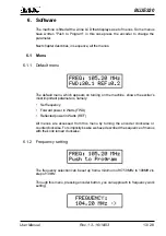
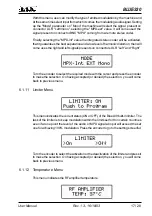
Page 17: ...urning on the machine shows the exciter s most important parameters namely Set frequency Forward power in Watts FWD Reflected power in Watts REF All menus are accessed from this menu by turning the en...

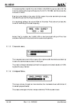
Page 18: ...for confirming or not new frequency Select Yes to confirm the LOCK LED on the front panel will go off for a few seconds until the VCO does not lock the new set up frequency 6 1 3 Channels menu The ins...

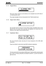
Page 19: ...bar limited modulation levels of the Blues30 When the audio source has been well adapted to the input level of the exciter or vice versa the bar should be empty 6 1 7 Impedance Menu The menu shows th...

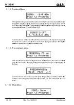
Page 20: ...n this screenful until the cursor reaches the required interval and then press the encoder to make the selection On having accepted or denied the selection you will come back to previous menu 6 1 9 Pr...

Page 21: ...on connectors XLR Left and Right Turn the encoder to select the required mode with the cursor and press the encoder to make the selection On having accepted or denied the selection you will come back...

Page 22: ...chine closes STATUS CTRL connector state You can set machine so that after a time interval with mute audio input an alarm signal comes activated To change parameters value enter in modify menu pressin...

Page 23: ...BLUES30 19 28 User Manual Rev 1 3 16 10 03 This operation can be made from qualified staff only following the appropriate instructions supplied from R V R Electronica...

Page 24: ...BLUES30 20 28 User Manual Rev 1 3 16 10 03 This page was intentionally left blank...

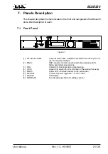
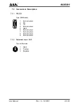
Page 25: ...lation monitoring Do not use it for spectral analysis 2 RS232 DB9 connector for interconnection with other devices and for factory parameters programming 3 PRG Yellow LED lit during machine programmin...

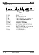
Page 26: ...mmer for SCA1 input level 10 MPXADJ Adjustment trimmer for MPX input level 11 AUXADJ Adjustment trimmer forAUX input level 12 L M 1 5dB Adjustment trimmer for Left or Mono channel audio input 13 R 1 5...

Page 27: ...03 7 3 Connectors Description 7 3 1 RS232 Type DB9 female 1 Not connected 2 RX 3 TX 4 Not connected 5 GND 6 Not connected 7 Not connected 8 Not connected 9 Not connected 7 3 2 Balanced input XLR Tipo...

Page 28: ...BLUES30 24 28 User Manual Rev 1 3 16 10 03 This page was intentionally left blank...

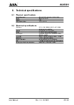
Page 29: ...ons Frequency 87 50 108 00 MHz 60 00 87 50 MHz special version available Stability 1 ppm from 10 C to 50 C Power 0 30 W continuously adjustable Audio Input L R Bal Unbal SCA AUX RDS Z10k 600 6 6dBm Au...

Page 30: ...BLUES30 26 28 User Manual Rev 1 3 16 10 03 This page was intentionally left blank...

Page 31: ...BLUES30 27 28 User Manual Rev 1 3 16 10 03 9 Modules Identifications 1 2 3 4 5 6 1 Logic Board 2 Main Board 3 Switching Power Supply 4 Input Board 5 Directional Coupler 6 R F Amplifier...

Page 32: ...BLUES30 28 28 User Manual Rev 1 3 16 10 03 This page was intentionally left blank...

Reviews: