HC2
28 / 30
User Manual
Rev. 1.1L - 07/07/03
two different positions, depending on the machine’s version:
•
directly on the splitter circuit
•
on two printed circuits boards that can be accessed from the front panel of the
coupler
In general, the rightmost capacitors are the ones used to adjust the RF path related
to the amplifier connected to the rightmost output connector of the coupler. For
reference, see the scheme silk.graphed on the rear panel of the HC2.
To efficiently adjust the capacitors, it is essential to use an isolated tool, e.g. a
plastic screwdriver.
The following procedures are optimized for adjusting the coupler in both cases.
8.3.1
Capacitors on the splitter circuit
1)
Remove the upper cover of the coupler
2)
Switch on the transmitter, having the exciter set on the working frequency
and at minimum power
3)
On the coupler, set the display for the visualization of forward power
4)
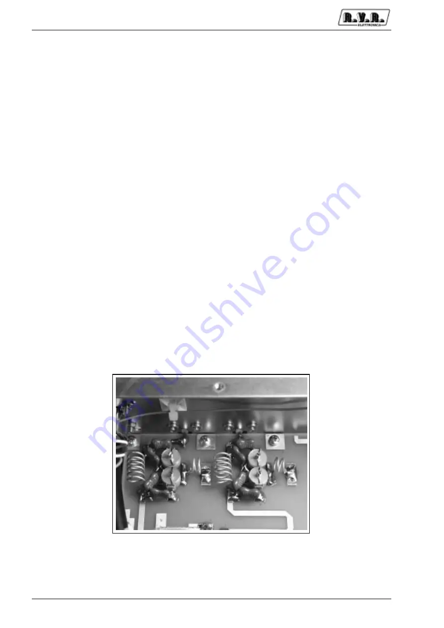
Set the variable capacitor in their middle position (Figure 3)
5)
Gradually increase the exciter power until the overall output power of the
transmitter reaches around the 80% of its nominal power
6)
Adjust the variable capacitors (1) and (2) (Figure 4) related to the amplifier
“A” (see the silk-graph on the rear panel of the coupler for reference), to
maximize the forward power measured in the coupler
Figure 3
7)
Adjust the variable capacitors (3) and (4) related to the amplifier “B”, still
maximizing the forward power measured by the coupler
Summary of Contents for HC2 LCD
Page 1: ...Manufactured by Italy HC2 LCD User Manual Volume 1...
Page 4: ...HC2 ii User Manual Rev 1 1L 07 07 03 This page was intentionally left blank...
Page 6: ...HC2 2 30 User Manual Rev 1 1L 07 07 03 This page was intentionally left blank...
Page 22: ...HC2 18 30 User Manual Rev 1 1L 07 07 03 This page was intentionally left blank...
Page 28: ...HC2 24 30 User Manual Rev 1 1L 07 07 03 This page was intentionally left blank...


