


13
13
ENGLISH
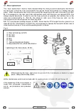
Specific references for the hydraulic machines
(*note 1 mod. hi)
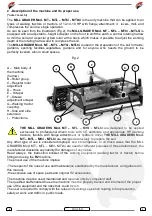
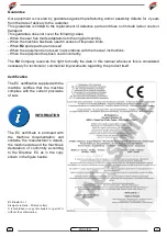
The power harrows MThi and MTLhi have been
designed to be applied to hydraulic machines
which have an oil pressure between 160 and
170 bar.
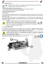
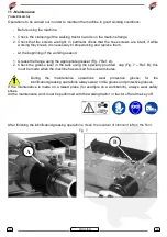
1 – Register adjustment roller(screw crank)
2 - Register adjustment roller support
3 – Hydraulic motor
Fig. 9
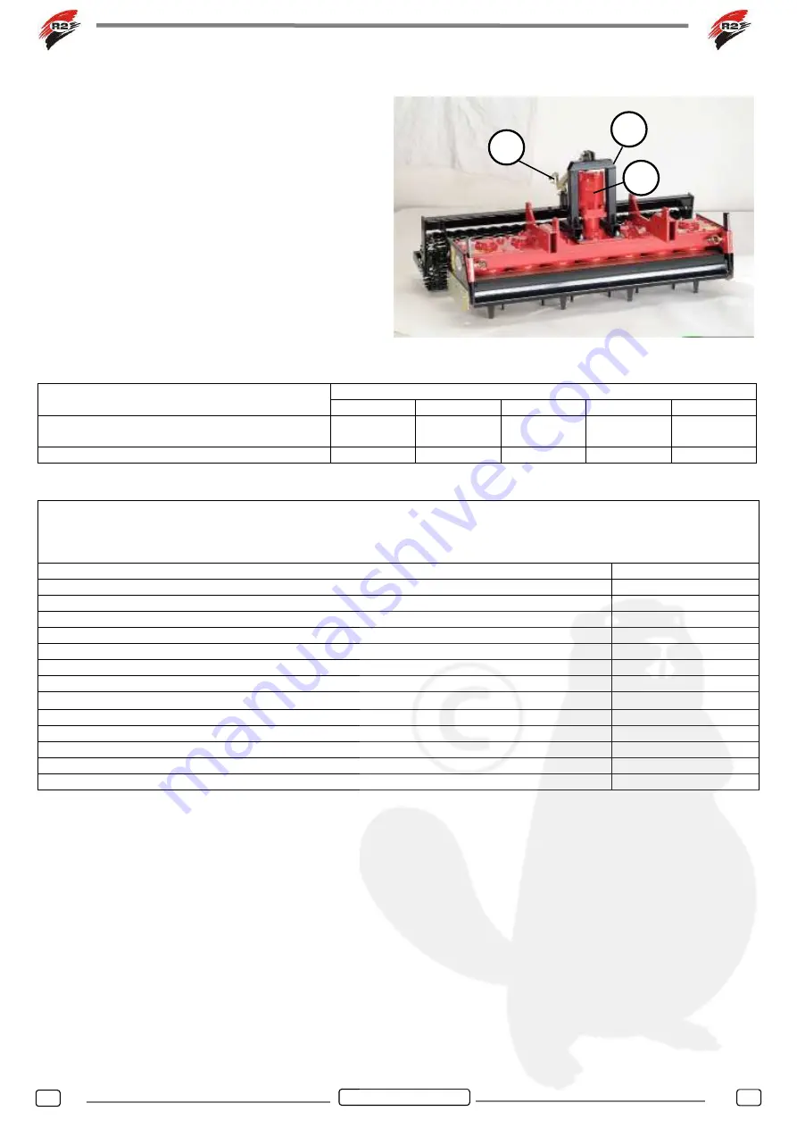
(*note 2 mod. hi)
Model
MTL 50 hi
MTL 75 hi
MTL 100 hi
MT 60 hi
MT 90 hi
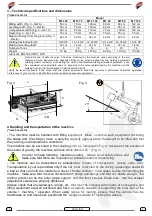
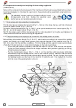
Maximum height from the ground (Fig. 5 – Ref
4)
70 cm
70 cm
70 cm
70 cm
70 cm
Oil pressure requested
150-180bar
150-180bar
150-180bar
150-180bar
150-180bar
Technical specifications of the hydaulic motor.
NOTE: the following data which concerns to the engine specifications are given by the manufacturer of the
hydaulic motor; for the specifications of the engine application to the R2 machine look at the previous table
and to the considerations of the following notes.
Data
Value (Cont. Funct.)
Geometric displacement (cm³/rev.)
102
Max input pressure (bar)
210
Max operating pressure (bar)
175
Max torque (daNm)
26
Max flow (l/min)
75
Max rotating speed (rpm)
735
Max power (kw)
17
Max cont. Return pressure without drain line (bar) 0 ÷ 100 rpm
75
Max cont. Return pressure without drain line (bar) 100 ÷ 300 rpm
50
Max cont. Return pressure without drain line (bar) > 300 rpm.
25
Max return pressure with drain line (bar)
140
Max starting pressure with no load (bar)
12
Min. starting torque (daNm) at max.
∆
P
21,5
1
2
3
Summary of Contents for MT Series
Page 18: ...18 18 NOTE...
Page 19: ......


