background image

ILLUSTRATIONS

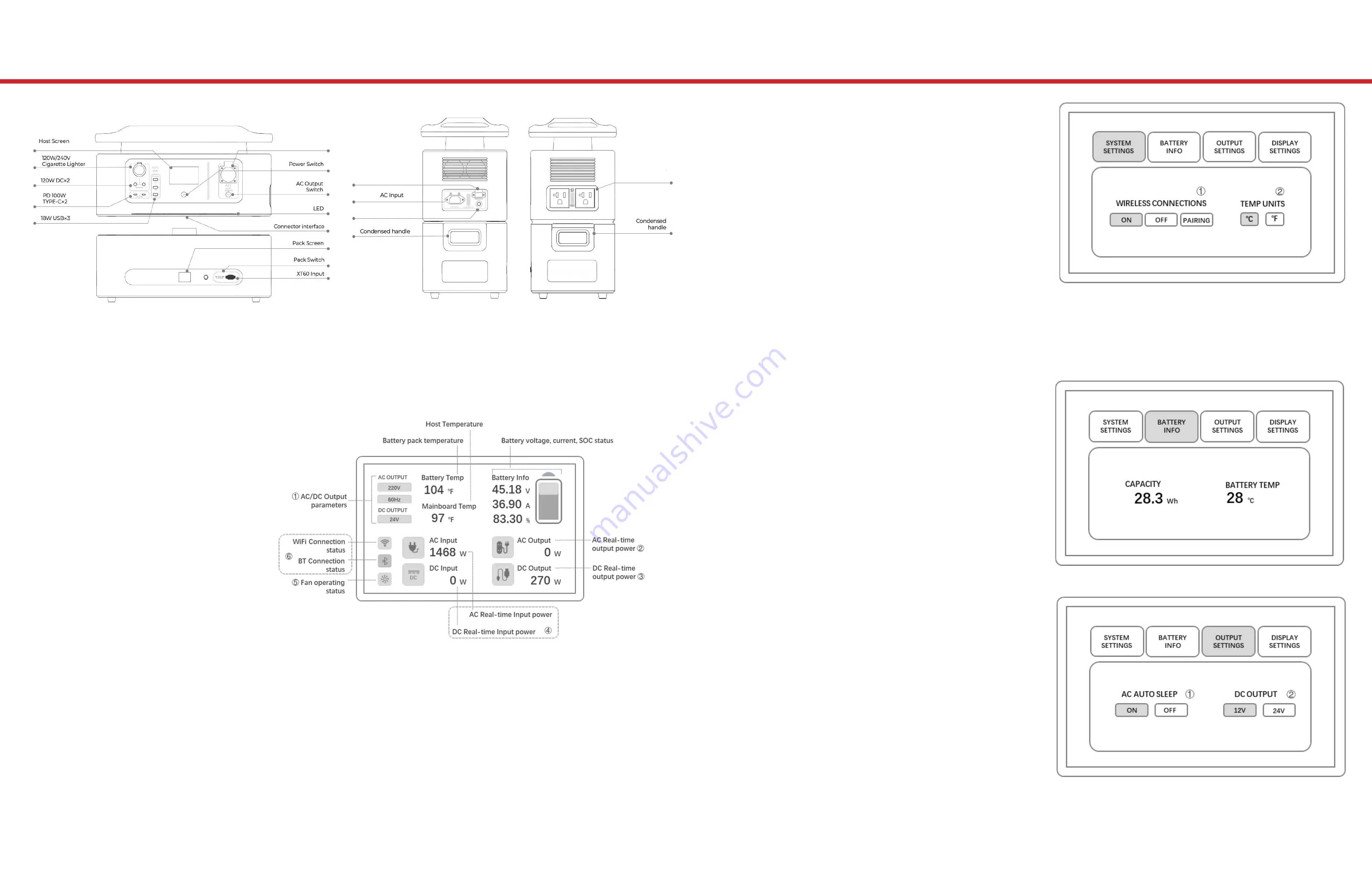
SYSTEM SETTINGS

1.  The Bluetooth and WiFi modules 

are integrated, and the switch 

settings are merged and named 

WIRELESS CONNECTIONS. 

2. When connecting to the APP, 

please select “Pairing” to pair and 

the “ON” icon will light up if paired 

successfully. When closing the 

wireless connection, please select 

the “OFF” icon and the “OFF” icon 

will light up.

3. The system display temperature 

can be viewed in “C” (Celsius) or 

“F” (Fahrenheit).

BATTERY INFORMATION

This diagram displays the 

remaining battery capacity and 

the current temperature inside of 

the battery pack.

OUTPUT SETTINGS

1.  AC Sleep Setting – If the Auto-

Sleep function is turned on, the 

AC turns off automatically. Sleep 

Conditions are as follows:

  a. The AC output load power is  

    less than 50W and the power  

    station has been on standy for  

    more than 5 minutes. 

  b. There is no DC Output and the  

    icon is off; and/or

  c. The indicator light turns off.

2. The DC output can be selected 

f rom “12V” and “24V”, and is 

connected to the DC5521 port. 

When the 24V voltage setting is 

selected, the DC5521 port turns off.

The following illustration outlines your power station’s primary 

external features. CAUTION! Inserting an unsupported accessory 

into the incorrect jack may result in damage to the device.

1.  The AC/DC Output 

Parameter displays the 

output DC voltage, AC 

voltage, and f requency.

2. When the AC switch is 

pressed, the AC Output 

icon lights up and 

displays the real-time 

AC output power after 

connecting with the AC 

electrical equipment.

3. The DC Output icon lights up and displays the real-time DC output 

power after connecting with the AC electrical equipment.

4. The AC/DC Input icon lights up and displays the AC/DC real-time 

input power after connecting with AC/DC charging.

5. The fan icon will not light up until the main host inverter has 

reached the set temperature.

6. The Bluetooth and WiFi icon will not light up until the network and 

device connect successfully.

MAIN SCREEN DISPLAY DETAILS AND EXPLANATIONS:

3600W

AC Output

30AMPS

2400W

AC Outputx2

20AMPS Each

1750W

800W Photovoltaic 

Input Port & 480W 

Max Car Input Port

Reset

Summary of Contents for RS3600

Page 1: ...RS3600 POWER STATION INTELLIGENT INVERTER 3600W V1 9 USER MANUAL...

Page 2: ...UED SPECIFICATIONS ILLUSTRATIONS SYSTEM SETTINGS DISPLAY SETTINGS AND CHARGING CAR CHARGING AND OUTPUT SAFETY INSTRUCTIONS DISPOSAL STORAGE PRIVACY DISCLAIMER WARRANTY AND TRADEMARK USER INFORMATION r...

Page 3: ...evisions or termination without prior notice Please visit www R3Di com to obtain the latest product information PRODUCT OVERVIEW TIPS FOR SAFETY 1 This product is not intended for use by children 2 Be...

Page 4: ...eeding 2000m or 6551ft 14 The AC output of this product is 220V Do not insert your hands or foreign objects into the AC sockets 15 Do not short circuit the output of this product 16 This product provi...

Page 5: ...nd 24V and is connected to the DC5521 port When the 24V voltage setting is selected the DC5521 port turns off The following illustration outlines your power station s primary external features CAUTION...

Page 6: ...nversion cable only They must also operate according to the instructions provided with the solar panel packaging Solar panels not provided by our company may not charge as expected or even cause damag...

Page 7: ...pment can be carried by the AC outlet and how many devices can be carried A The rated AC output power of this product is 3000W It is recommended that the total power of all electrical equipment is low...

Page 8: ...tter and people and dispose of it in accordance with local laws and regulations DISPOSAL GUIDE 1 The product contains batteries with potentially dangerous chemicals so it is strictly prohibited to dis...

Page 9: ...LIMITED WARRANTY The full ATEL USA and R3Di Warranty Policy can be found at www R3Di com warranty On this page you can learn how to Start a Warranty Claim Check on an Existing Claim and read the Warr...

Page 10: ...USERNAME TELEPHONE POSTAL CODE PRODUCT PRODUCT TYPE E MAIL DESCRIBE FAILURE SEQUENCE CODE USER ADDRESS SALES INFORMATION DATE OF PURCHASE SALES UNIT INVOICE TELEPHONE SALES ADDRESS CONTACT SUPPORT R3...

Reviews: