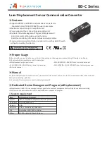
Laser Displacement Sensor Communication Converter
-|Transparent setting
guide|-
▣
Connections
◎ RS232C communication
Pin Name Description
1
N.C.
None
2
TXD
Converter output
3
RXD
Converter input
4
N.C.
None
5
GND
Ground
6
N.C.
None
7
N.C.
None
8
N.C.
None
9
N.C.
None
Pin
Name
1
CD
2
RD
3
SD
4
ER
5
SG
6
DR
7
RS
8
CS
9
CI
FG
BD-C
External device
When connecting BD-C
to external device, use
D-SUB 9 pin cable.
1
6
2
3
4
5
7
8
9
1
6
2
3
4
5
7
8
9
◎ RS485 communication
Pin
Name Description
1
A(+)
RS485 + signal
2
B(-)
RS485 - signal
Communication pin
Terminating switch
Set the switch to 'RT' when the communication
converter is connected to the terminal of RS485
communication connection, and set to 'OFF' when it is
in the middle of the communication connection.
1
A B
2
Application of system organization
Computer
B(-)
A(+)
A(+) B(-)
A(+) B(-)
A(+) B(-)
Terminating resistance
(100 to 120Ω)
RS485
DEVICE
#1
RS485
DEVICE
#2
RS485
DEVICE
#31
RS485
DEVICE
#32
USB/Wi-Fi - RS485
Communication
converter
B(-)
RT
OFF
A(+)
RT
OFF


