background image

Laser Displacement Sensor Communication Converter

-|Transparent setting 

guide|-

Installations

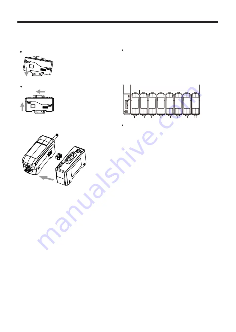
◎ Mounting on DIN rail

◎ Communication system composition

◎ Connecting to amplifier unit

 Mounting

①  Insert bottom holder of 

communication converter to 35mm 

width DIN rail.

②  Push the front part of the unit to 

arrow direction to mount.

 Detaching

①  Side amplifier unit to ⓐ direction.

②  Pull the assembly part to ⓑ direction

to detach.

① Remove the side cover at the connecting side.

② Connect the side connector to the units.

③ After mounting amplifier unit and communication unit on 

DIN rail, push it to arrow direction tightly.

※In case of disconnecting, follow the upper sequence reversely.

 Precautions when connecting amplifier unit

• Mount on DIN rail.

•  Do not supply the power when adding amplifier unit.

•  Supply power to each connected amplifier unit at the same 

time.

•  Up to 8 amplifier units can be connected, and only 1 calculation

function can be performed per 1 group of mutually connected 

amplifiers.

•  When the calculation function is activated, the setting values 

(SV) of the slave units are disable and the mutual interference 

prevention function for sensor heads is executed automatically.


 Distinguishing master/slave amplifier units

  When the power cable direction is down, the amplifier at the 

left end is the master unit, and the channel number of slaves 

increases sequentially to the right.

Communication converter is connected to the left side of 

master amplifier unit.

Comm.

converter

Amplifier unit

MAS

TER

SL

AVE 1

SL

AVE 2

SL

AVE 3

SL

AVE 4

SL

AVE 5

SL

AVE 6

SL

AVE 7

Master

Slave

※Max. 8 units

Summary of Contents for BD-C Series

Page 1: ...load manuals Proper Usage Before using the communication converter unit depending on the usage environment keep following items handy Visit our web site www autonics com to download atDisplacement program manual SCM 38I RS232C RS485 Driver Instruction manual SCM US48I USB RS485 Driver Instruction manual SCM WF48 Wi Fi USB RS485 Driver Instruction manual BD Series manual Dedicated Device Management...

Page 2: ... weight The temperature or humidity mentioned in Environment indicates a non freezing or condensation environment BD C Series Communication Converter Model BD CRS Power supply 1 Power consumption Max 2 3W Communication function RS 232C RS 485 Communication speed 9600 19200 38400 115200bps default Indication 4 LED status indicators Function Real time monitoring Executes every BD Series feature and ...

Page 3: ...ly Communication output indicator TX Green Displays communication output status from communication converter to external device Communication input indicator RX Green Displays communication input status from communication converter to external device Communication error indicator ERROR Red Displays the communication status of communication converter 4 Communication Setting Switch Sets communicatio...

Page 4: ...SUB 9 pin cable 1 6 2 3 4 5 7 8 9 1 6 2 3 4 5 7 8 9 RS485 communication Pin Name Description 1 A RS485 signal 2 B RS485 signal Communication pin Terminating switch Set the switch to RT when the communication converter is connected to the terminal of RS485 communication connection and set to OFF when it is in the middle of the communication connection 1 A B 2 Application of system organization Comp...

Page 5: ...ommunication converter It is calculated in binary according to the ON OFF status of each switch Switch No Switch3 Switch4 Switch5 Switch6 Switch7 Address Binary digit OFF 0 ON 1 2 4 2 3 2 2 2 1 2 0 Address Switch 3 2 4 Switch 4 2 3 Switch 5 2 2 Switch 6 2 1 Switch 7 2 0 1 Address 1 OFF OFF OFF OFF OFF 1 0 2 4 0 2 3 0 2 2 0 2 1 0 2 0 1 Address 2 OFF OFF OFF OFF ON 2 0 2 4 0 2 3 0 2 2 0 2 1 1 2 0 1 ...

Page 6: ...necting amplifier unit Mount on DIN rail Do not supply the power when adding amplifier unit Supply power to each connected amplifier unit at the same time Up to 8 amplifier units can be connected and only 1 calculation function can be performed per 1 group of mutually connected amplifiers When the calculation function is activated the setting values SV of the slave units are disable and the mutual...

Page 7: ...TX Green Displays communication output status from communication converter to external device Status Reason Solution Flashing Signal is outputting Off Signal is not outputting Communication input indicator RX Green Displays communication input status from communication converter to external device Status Reason Solution Flashing Signal is inputting Off Signal is not inputting Communication error i...

Reviews: