-22-
NL
DK
A
B
D
C
236 mm
9.29"
217 mm
8.58"
217 mm
8.58"
15 mm
0.59"
1
2
3
C
A
s. 450
485 mm 19.09"
236 mm
9.29"
180 mm
7.09" 236 mm 9.29"
217 mm
8.58"
177 mm
6.27"
217 mm
8.58"
140 mm
5.51"
485 mm
19.09"
500 mm
19.68"
PRÆSENTATION AF
INDKAPSLET SLANGETROMLE
Fastmonteret og drejelig slange-
tromle, fås i:
- lakeret stål
20 bar/290 psi,
150 bar/2175 psi,
600 bar/8700 psi
- leveres med og uden slange.
MONTERING AF
SLANGETROMLE
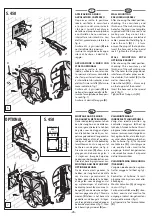
Mulige positioner:
Vægmonteret i position [A] og [B]
til brug enkeltvist eller installation
i linie.
Position [C] på arbejdsbænk eller
gulv.
Loftsmonteret i position [D].
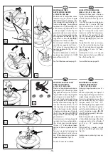
MONTERING AF KONSOL
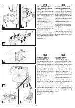
Montér konsollen [A] på slange-
tromlen (fig. 1). Indsæt de seks
skruer og fastgør dem i rækkefølge
(fig. 2).
Anbring herefter hjørnepropperne
af plast [C] i de ubenyttede huller
[C] (fig. 3).
PRESENTATIE VAN DE
SLANGHASPEL MET BEHUIZING
Vaste en wendbare slanghaspel,
verkrijgbaar in:
gelakt staal
20 bar/290 psi,
150 bar/2175 psi,
600 bar/8700 psi
geleverd met of zonder slang.
INSTALLATIE VAN DE
SLANGHASPEL
Mogelijke plaatsen:
[A]-[B] aan de muur voor
afzonderlijk gebruik of als set;
[C] op de werkbank of op de vloer;
[D] aan het plafond.
MONTAGE VAN DE BEUGEL
Maak beugel [A] aan de slanghas-
pel vast (fig. 1).
Breng de 6 schroeven aan door ze
op volgorde te bevestigen (fig. 2).
Breng vervolgens de kunststof
hoekdoppen [C] op de vrije gaten
aan (fig. 3).
PRESENTATION
ENCLOSED HOSE REEL
Fixed and swivel hose reels, avail-
able in:
painted steel
20 bar/290 psi,
150 bar/2175 psi,
600 bar/8700 psi
supplied with and without hose.
HOSE REEL INSTALLATION
Possible positions:
[A]-[B] wall mounted for single use
or in banks.
[C] on bench or floor.
[D] ceiling mounted.
FITTING THE BRACKET
Fix bracket [A] to the hose reel
(fig. 1).
Impress the 6 screws, fixing them
in sequence (fig. 2).
Then apply the plastic plugs [C] in
the free holes (fig. 3).
PRESENTAZIONE
AVVOLGITUBO CARTERATO
Avvolgitubo fisso e orientabile,
disponibile in:
acciaio verniciato
20 bar/290 psi,
150 bar/2175 psi,
600 bar/8700 psi
fornito con e senza tubo.
INSTALLAZIONE
DELL'AVVOLGITUBO
Posizioni possibili:
[A]-[B] a muro per utilizzo singolo
o in batteria.
[C] a banco o a pavimento.
[D] a soffitto.
APPLICAZIONE DELLA STAFFA
Fissare la staffa [A] all'avvolgitubo
(fig. 1).
Improntare le 6 viti fissandole in
sequenza (fig. 2).
Applicare poi ai fori liberi i tappi
angolari in plastica [C] (fig. 3).
s. 440
564 mm
22.20"
485 mm 19.09"
164 mm 6.46"
164 mm
6.46"
118 mm
4.65"
208 mm
8.19"
140 mm
5.51"
162 mm
6.38"
208 mm
8.19"
485 mm
19.09"
Summary of Contents for s. 290
Page 50: ... 50 Notes ...
Page 51: ... 51 Notes ...


