


82
Rabbit 2000 Microprocessor
7.8 System Reset
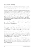
The Rabbit has a master reset input (/RESET), which initializes everything in the device
except for the RTC. This reset is delayed until the completion of any write cycles in
progress to prevent any potential corruption of memory. If no write cycles are in progress,
the reset takes effect immediately.
The purpose of inhibiting the completion of reset until write cycles in progress are com-
pleted is to protect variables in battery-backed memory from corruption when a reset takes
place. However, if the power controller responsible for battery switchover blocks the chip
select signal to the RAM, the writes in progress will be aborted in any case. This is not
necessarily serious as software schemes can be used to protect critical variables in battery-
backed memory.
The reset sequence requires a minimum of 128 cycles of the fast oscillator to complete,
even if no write cycles were in progress at the start of the reset. Reset forces both the pro-
cessor clock and the peripheral clock in the divide-by-eight mode. Note that if the proces-
sor is being clocked from the 32 kHz oscillator, the 128 cycles of the fast oscillator will
probably not be sufficient to allow any writes in progress to be completed before the reset
sequence completes and the clocks switch to divide-by-eight mode.
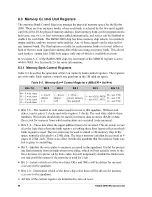
During reset, all of the memory control signals are held inactive. After the /RESET signal
is inactive (high), the processor begins fetching instructions and the memory control sig-
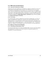
nals begin normal operation. Note that the default values in the Memory Bank Control
registers select four wait states per access, so the initial program fetch memory reads are
48 clock cycles long (8 x (2 + 4)). Software can immediately adjust the processor timing
to whatever the system requires.
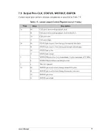
The default selection for the memory control signals consists of /CS0, /OE0 and /WE0,
and writes are enabled. This selection can also be immediately programmed to match the
hardware configuration. A typical sequence would be to speed up the clock to full speed,
then select the appropriate number of wait states and the chip select signals, output enable
signals and write enable signals. At this point software would usually check the system
status to determine what type of reset just occurred and begin normal operation.
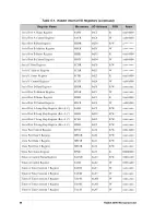
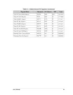
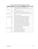
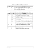
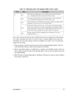
Table 7-10 describes the state of the I/O pins after an external reset is recognized by the
Rabbit CPU. Note that the /RESET signal must be held low for three clocks for the proces-
sor to begin the reset sequence. There is no facility to tri-state output lines such as the
address lines and the memory and I/O control lines.
Summary of Contents for 2000
Page 1: ...Rabbit 2000 Microprocessor User s Manual 019 0069 041018 M...
Page 12: ...6 Rabbit 2000 Microprocessor...
Page 46: ...40 Rabbit 2000 Microprocessor...
Page 54: ...48 Rabbit 2000 Microprocessor...
Page 76: ...70 Rabbit 2000 Microprocessor...
Page 96: ...90 Rabbit 2000 Microprocessor...
Page 142: ...136 Rabbit 2000 Microprocessor...
Page 154: ...148 Rabbit 2000 Microprocessor...
Page 170: ...164 Rabbit 2000 Microprocessor...
Page 174: ...168 Rabbit 2000 Microprocessor...
Page 180: ...174 Rabbit 2000 Microprocessor...
Page 202: ...196 Rabbit 2000 Microprocessor...
Page 206: ...200 Rabbit 2000 Microprocessor...
Page 226: ......
Page 230: ...224 Rabbit 2000 Microprocessor...


