


EM1500 User’s Manual
39
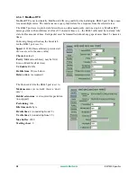
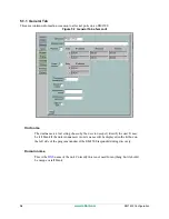
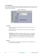
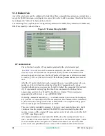
LED shows Tx/Rx state in run mode
Each serial port has a checkbox here. Check each one that you want to have effect the
user LED. When a serial port is checked here and the unit is in normal run mode, the
user LED blinks red when data is transmitted and blinks green when data is received.
Please note that there is only one bicolor LED for all of the serial ports; i.e., the user
LED will light up whenever one or more of the serial ports checked here is receiving
or transmitting.
The user LED also gives status for the unit as a whole. Please see
for a
description of the possible LED patterns.
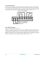
5.1.2.1 Additional Information for Auxiliary I/O
The GUI allows you to change the initial state of PF0-4, OUT0, OUT1 and the relay, but it does not allow
you to change the initial state of the three digital inputs on the 9-pin connector. The default state is “pulled
up.” To change the state to “pull-down” means moving the zero ohm resistor at JP1, which will require
some soldering. For directions on how to access JP1, please see
Summary of Contents for EM1500
Page 14: ...10 www rabbit com Introduction...
Page 22: ...18 www rabbit com Getting Started...
Page 76: ...72 www rabbit com EM1500 Configuration...
Page 90: ...86 www rabbit com EM1500 Specifications...
Page 104: ...100 www rabbit com Serial and TCP Protocols...
Page 118: ...114 www rabbit com EM1500 FAQ...


