KORMORAN PL V 180 / PL VHA 180
OPERATING
INSTRUCTIONS
- 25 -
9901.00.23EN00 - 01/2016
CAUTION:
Before hooking the top link in, ensure that the space
between the implement fastening and the tractor's
ERWWRPOLQNLVVXI¿FLHQWO\ODUJHWRHQVXUHWKDWWKHUH
are no points of contact between the raised and
working positions. A second check must be carried
RXWLQWKH¿HOGRQFHWKHLPSOHPHQWLVXQGHUUHDO
working conditions.
IMPORTANT:
If the coupling is not horizontal, use the turning
cylinder to position it this way. This makes coupling
easier.
6.1.3
Unlocking the latch
CAUTION:
A locking bolt breaks if the latch is forgotten when
raising the bearing rail.
IMPORTANT:
Never remain in front of or near to this bolt during
the coupling procedure. Projections caused by
a break can lead to severe injuries.
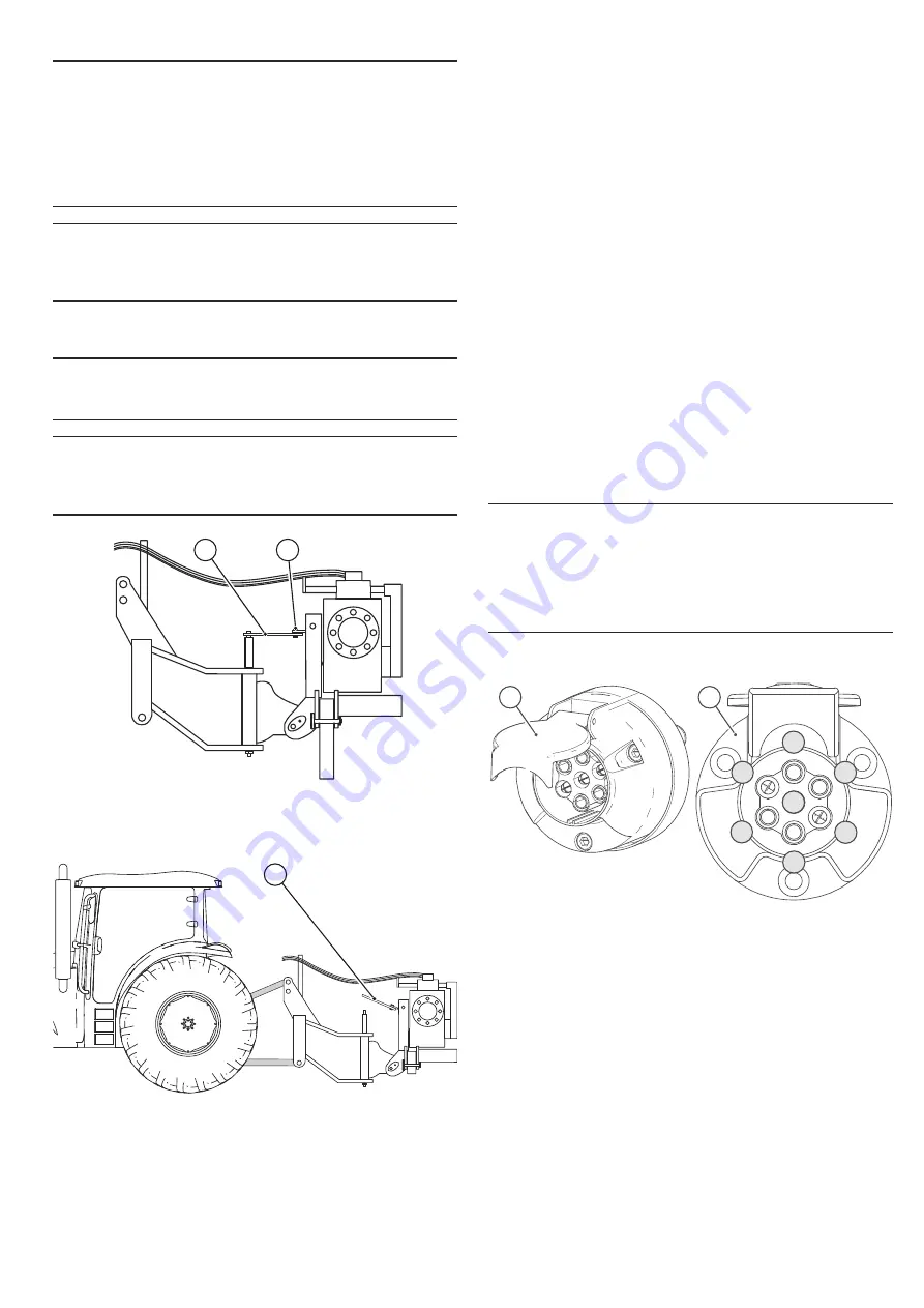
1
2
Key
1
Latch in uncoupled position
2 Locking
bolts
1
Key
1
Latch in coupled position
ʈ
$OORIWKHVHPLPRXQWHGSORXJKVIURQWD[OHVDUHKHOGLQWKH
uncoupled position by a latch.
ʈ
As soon as the bottom links are coupled correctly, use the
tractor's lifting function to lift the coupling head, in order to
unlock the latch.
ʈ
As soon as the latch is completely free, raise it and lock it into
the top position (remove the spring pin and then the bolt, raise
the latch and then re-insert the spring pin and the bolt to hold
the latch in the top position).
ʈ
Now hook the top link in.
6.1.4
Hooking the top link in
As soon as the tractor's bottom links are coupled correctly and
the latch is unlocked, connect the top link.
Raise the implement and ensure that there can be no contact
with the tractor.
Move the supports into the working position.
Position the support in working mode:
-
5HPRYHWKHORFNLQJSLQDQGWKHD[OHURWDWHWKHVXSSRUW
XSZDUGVLQVHUWWKHD[OHDQGWKHORFNLQJSLQDJDLQWRORFNWKH
support into the top position.
IMPORTANT:
Ensure that the clearance between the implement
IDVWHQLQJDQGWKHWRSOLQNVEROWLVVXI¿FLHQWWR
ensure that there are no points of contact between
the raised and working positions. Carry out a
VHFRQGFKHFNDWWKHZRUNLQJORFDWLRQ¿HOGRQFHWKH
implement is under real working conditions.
6.1.5
Electrical connection for signals
7
1
2
3
4
5
6
A
B
Key
A Socket
B
Pin assignment (viewed from the front)
1
Left indicator (yellow)
2 Free
3 Earth
(white)
4
Right indicator (green)
5
Right tail light (brown)
6
Brake light (red)
7
Left tail light (black)
ʈ
Connect the lighting cable to the tractor's socket.
6.1.6 Hydraulic
connections
ʈ
See
§
7.


