background image

Racepak

Racepak

Racepak

Racepak    

949-709-5555 

www.Racepak.com


Hardware Installation: Driveshaft Sensor 

and Collar

A drive shaft rpm sensor and mounting bracket used to mount the sensor to the vehicle are included in the 

Sportsman Kit. However, the drive shaft split collar is sold separately. These collars can be purchased direct from 

Racepak and are offered in many different sizes to accommodate multiple yoke configurations. These collars are 

available with either two or eight magnets. The rpm sensor is a magnetically sensitive sensor that is polarity 

sensitive each time a magnet passes in close proximity.

The first step in installing the kit is to determine where the split collar will be mounted.  Normally the split collar is 
mounted  on  the  pinion  shaft/yoke.    However,  it  can  also  be  mounted  on  the  transmission  tail  shaft/yoke.    If  your 
transmission and/or bell housing is removed frequently, you should mount the collar on the pinion shaft/yoke. Thus 
avoiding possible damage to the sensor during clutch, and/or transmission service. 

After  you  have  selected  a  location,  position  the  split  collar  over  the  shaft,  and  fix  the  collar  onto  the  shaft  by 
tightening the two bolts connecting the two collar halves.  Tighten the two bolts equally such that the gap on both 
sides of the split collar is equal.  This will ensure the magnets are 180 degrees apart. 

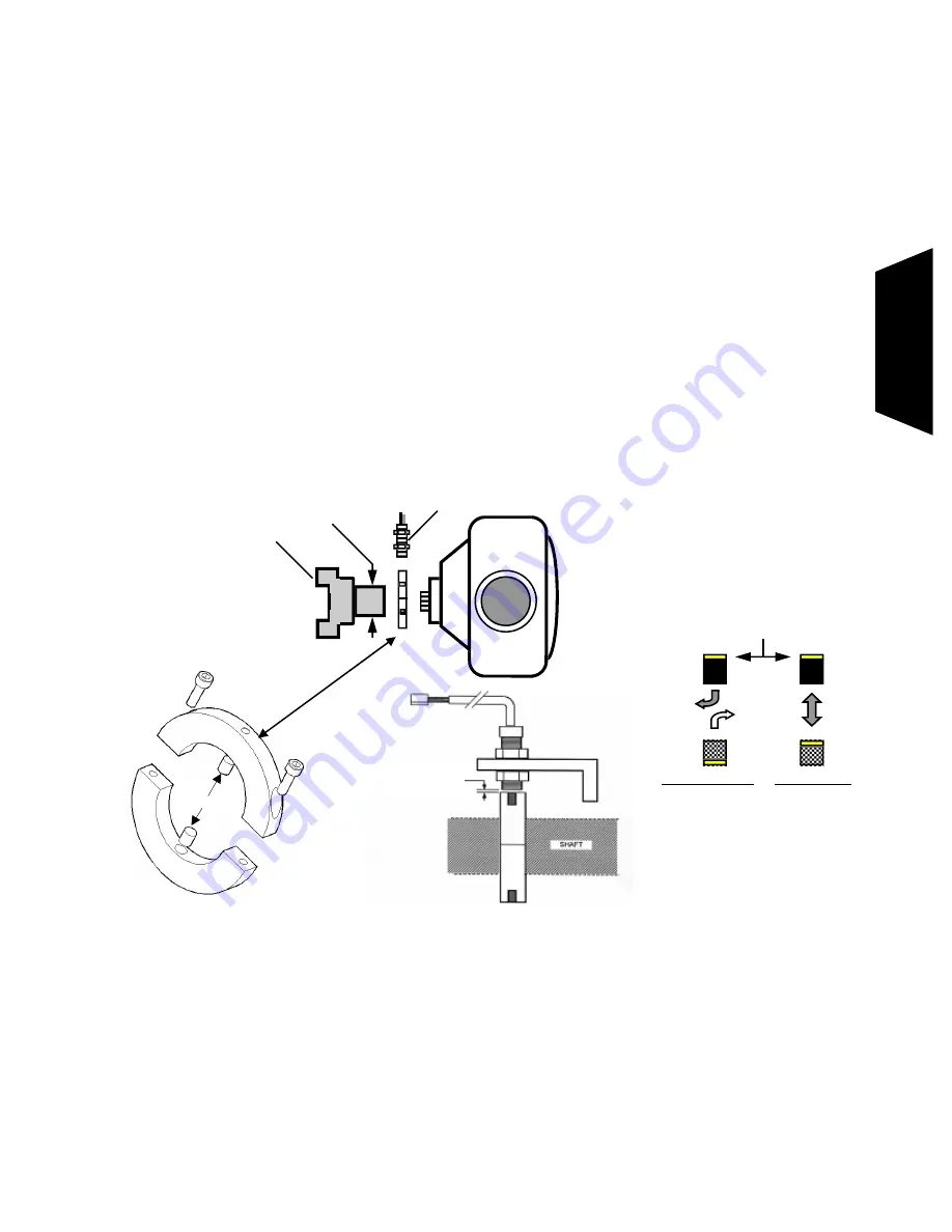
Next, secure the  mount bracket, and rpm sensor to the vehicle as shown below.  The mount  must be installed to a 
solid  member  of  the  vehicle  that  does  not  move  relative  to  the  placement  of  the  split  collar  assembly.    This  will 
prevent  contact  between  the  sensor  and  the  split  collar.    Insert  the  rpm  sensor  in  the  slotted  hole  in  the  mount 
bracket,  and    position  the  rpm  sensor  such  that  the  sensor  is  centered  over  the  magnet  in  the  split  collar.    Next, 
adjust the gap between the end of the rpm sensor and the split collar between .050” to .100”.  Secure the sensor by 
tightening the two jam nuts located on the sensor. 

NOTE: SPLIT COLLARS ON CARS USING A COUPLER 

When the driveline is equipped with a coupler rather than a U-joint, the best location for mounting the split collar often changes. Because most of the 
couplers have the female portion mounted on the pinion, and the radius on the backside tapers right to the pinion seal, this does not leave any room to 
mount a split collar in the traditional location. In this case, we must move the split collar forward onto the male portion of the coupler. 

When mounting the split collar on the male half of the coupler a new problem arises. This portion of the coupler needs to have some longitudinal 
movement in order to function properly. It must be able to slide forward and backward a small amount. This presents a problem for the split collar in 
trying to keep the magnets positioned under the sensor. When the magnet moves out from under the sensor, the signal is lost and the drive shaft RPM 
is  not  recorded.  In  order  to  avoid  this  problem,  Racepak  has  made  collars  that  contain  two  pairs  of  magnets  (total  of  4).  Each  pair  of  magnets  is 
mounted longitudinally (inline) on the collar, which allows it some freedom to move without the sensor losing contact with a magnet.  In most cases, 
the male portion of the coupler will have two outside diameters.  

These collars are sold separately and are available directly from Racepak. 

8

Note: 

If you are using a collar other 

than the one supplied by Racepak 
you can use the supplied magnet 
with the sensor to test the polarity 
of the magnets in the collar 

.050 to .100 clearance 

between sensor and magnet 

Sensor

U-Joint Yoke

Rear 

End 

MEASURE YOKE  

O.D. HERE

Yellow Painted End 

INCORRECT 

Magnets 
will repel 

each other 

CORRECT 

Magnets 

will attract 

each other 

Magnets 

Yoke is shown separated from pinion. 

In most cases, installation does not 

require yoke to be removed 

H

a

rd

w

a

re


In

st

a

ll

a

ti

o

n


Summary of Contents for 610-KT-SPRTMN

Page 1: ...Installation and Operation Manual 610 KT SPRTMN 949 709 5555 30402 Esperanza Rancho Santa Margarita CA 92688 USA Fax 949 709 5556 www racepak com...

Page 2: ...actured by Competition Systems Inc Racepak against defects in workmanship or material for a period of six months after the date of purchase This warranty applies to the first retail purchaser and cove...

Page 3: ...ring Communication Port Serial Port 14 IV Configuring the Sportsman Data Logger 15 Modifying and Saving the configuration file 15 Adding or Removing V Net Devices on the Sportsman 19 V Operating the S...

Page 4: ...h the system After you have installed the particular device in your system you will be asked to insert the instruction sheet in one of the Appendix in this manual It is extremely important that you do...

Page 5: ...Input Wiring Harness D USB Stick with DataLink II Software and manuals E Hall Effect Driveshaft Sensor F Universal Driveshaft Sensor Bracket G SD Memory Card H Serial Port Plug I USB to Serial Adapto...

Page 6: ...ge illustrate the location of the input connectors on the Sportsman data logger You probably noticed we mentioned four terms digital inputs analog inputs hardwired inputs and V Net devices You may alr...

Page 7: ...ata Flashing Red Data recording is in progress Flashing Green Writing data to memory card Flashes green every 3 seconds while recording Solid Orange SD memory card error There is problem with the memo...

Page 8: ...RPM 12V EVENT CONNECTOR A B C D Clear Wire Orange Wire Red Wire Black Wire 12 Volt Event input connect to 12 volts to mark event Driveshaft Signal Input connects to driveshaft sensor Driveshaft 12 pow...

Page 9: ...main devices data loggers display dashes and EGT boxes to V Net cables and or modules in the complete system The design of the tee allows modules to be located in both directions from the data logger...

Page 10: ...Avoid mounting the recorder directly near the ignition box or any other electronic ignition components Try to maintain a minimum of 18 inches of clearance between the recorder and any of these items 4...

Page 11: ...the gap between the end of the rpm sensor and the split collar between 050 to 100 Secure the sensor by tightening the two jam nuts located on the sensor NOTE SPLIT COLLARS ON CARS USING A COUPLER Whe...

Page 12: ...aft Ground connects to driveshaft sensor Secondary Digital Input Wiring Harness DS RPM 12 VOLT EVENT The Secondary Digital Input will use a wiring harness containing 1 color coded wire by itself and 3...

Page 13: ...the connector through the supplied yellow fuse holder Strip the red wire back approximately inch and double over the end of the stripped wire Insert the wire in the fuse terminal lug and crimp as show...

Page 14: ...inal on wire and connect to the push button Once the wire is stripped crimp a spade terminal on wire and connect to chassis ground or negative battery Blue wire found in Main Power Digital Input Wirin...

Page 15: ...ut Wiring Harness can be used to mark a single 12 volt event such as but not limited to transbrake activation brake switch activation or solenoid activation Any time this wire is supplied with 12 volt...

Page 16: ...where they are continually exposed to water and or high pressure sprays When you are satisfied the devices can be installed meeting the above criteria follow the steps below to install the V Net devic...

Page 17: ...tcut icon will be added to your desktop with a title Datalink Program Double click on the icon to start the Datalink II software Configuring the Sportsman Serial Communications Port You will be connec...

Page 18: ...d open the car configuration file created for your system 3 Select the device channel to be modified 4 Make the desired modifications to the device channel 5 Apply power to your data logger system 6 S...

Page 19: ...ur sample DS RPM Click the right mouse button and a edit dialog box as shown below will be opened to allow you to edit the parameters for that specific device channel In addition to allowing you to ed...

Page 20: ...n factors for the sensor connected to this channel These factors are entered automatically by the system any time the Sensor type is selected They must be entered manually only when a custom sensor ca...

Page 21: ...s box will be displayed to indicate whether the transfer is successful When you have successfully sent the new information to the device being programmed select the OK button to exit the dialog box As...

Page 22: ...ules in your system and will read in the current configuration of the system During this process a message log dialog box will be displayed The progress of the read will be displayed in the message lo...

Page 23: ...d that you maintain the correct time in your Sportsman The time can be changed by performing the following procedure Before beginning ensure that the time and date on your PC are set correctly The tim...

Page 24: ...ighly recommended that you do not allow too many run data files to build up Storing too many data files on the memory card can also make it more difficult to identify the proper run data file on futur...

Page 25: ...s recording immediately after power up and records data until the maximum record time is reached or the power is turned off Start Recording Manually on Operator Input In this mode a momentary push but...

Page 26: ...n channel button and click the right mouse button shown below left The logger edit dialog box will be displayed shown below right Located in the lower left hand corner of the dialog box is the Systems...

Page 27: ...red If you have selected any other channel the recording will start any time the value of the selected channel exceeds the value of the record threshold If you are using an on off switch connected to...

Page 28: ...start In addition if you are trying to take a warm up recording in the pits be sure the data channel exceeds the start threshold or no recording will be taken After you have recorded your data you ar...

Page 29: ...details icon in the upper corner The time and date will now be shown However they typically cannot be seen because they are off to the right of the screen To fix this you will need to drag the window...

Page 30: ...nformation will be used to name the data file The dialog box is shown below If you need help on filling out the dialog box click on the help icon in the upper left hand corner of the dialog box Select...

Page 31: ...s to be monitored should be equal to or greater than the real time sample rate If they are not then the last data points will be repeated during the sample process Next select the Real Time Communicat...

Page 32: ...help button Icon located in the upper left hand corner of the dialog box Select Next and depending on your configuration file additional dialog boxes may be displayed These are part of the Run Log se...

Page 33: ...button in the same manner you display data from a recorded file To stop the data acquisition left click on the Stop Data Acquisition icon located at the bottom of the tool bar The real time data acqu...

Page 34: ...Racepak Racepak Racepak Racepak 949 709 5555 www Racepak com 31 Appendix I V Net Module Installation Instructions Appendix...

Page 35: ...Racepak Racepak Racepak Racepak 949 709 5555 www Racepak com...

Page 36: ...949 709 5555 30402 Esperanza Rancho Santa Margarita CA 92688 USA Fax 949 709 5556 www racepak com Rev 3a 4 09 MANL INTL Sport...

Reviews: