- 76 -
8. Trouble shooting
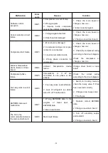
8. 1 Error code display on LED wire controller
Malfunction
Error
code
Reason
Solution
Inlet water temperature
sensor failure
PP01
1. The sensor in open or short
circuit
2. The wiring of sensor is loose
1. Check or change the sensor
2.Re-fix the wiring of the
sensors
Outlet water temperature
sensor failure
PP02
1. The sensor in open or short
circuit
2. The wiring of sensor is loose
1. Check or change the sensor
2.Re-fix the wiring of the
sensors
Heating piping sensor
failure
PP03
1. The sensor in open or short
circuit
2. The wiring of sensor is loose
1. Check or change the sensor
2.Re-fix the wiring of the
sensors
Gas return sensor failure
PP04
1. The sensor in open or short
circuit
2. The wiring of sensor is loose
1. Check or change the sensor
2.Re-fix the wiring of the
sensors
Ambient
temperature
sensor failure
PP05
1. The sensor in open or short
circuit
2. The wiring of sensor is loose
1. Check or change the sensor
2.Re-fix the wiring of the
sensors
Exhaust piping sensor
failure
PP06
1. The sensor in open or short
circuit
2. The wiring of sensor is loose
1. Check or change the sensor
2.Re-fix the wiring of the
sensors
Antifreeze protection in
Winter
PP07
Ambient temperature or water inlet
temperature is too low
Normal protection
Low ambient temperature
protection
PP08
1.Beyond the scope of using
environment
2. Sensor abnormality
1. Stop using, beyond the
scope of using
2.Change the sensor
Piping temperature too
high
protection
under
cooling mode
PP10
1. Ambient temperature is too high
or the water temperature is too high
in cooling mode
2. Refrigeration system is abnormal
1. Check the scope of using
2. Check refrigeration system
T2 water temp. Too low
protection under cooling
mode
PP11
1. Low water flow
2. T2
temperature
sensor
abnormal
1. Check water pump and
waterway system
2. Change T2 temperature
sensor
High pressure failure
EE01
1. Ambient temperature is too high
2. Water temperature is too high
3. Water flow is too low
Fan motor speed is abnormal, or
fan motor has damaged
1. Check the water flow or
water pump
2. Check the fan motor
3. Check and repair the piping
system
Summary of Contents for INVERTER 11
Page 1: ...POMPE CHALEUR DE PISCINE D RACER INVERTER NOTICE D INSTALLATION ET D UTILISATION...
Page 2: ......
Page 6: ...3 2 Dimension 2 1 Dimension Mod les RACER INVERTER 7 9 KW...
Page 7: ...4 Mod les RACER INVERTER 11 14 16 KW Mod les RACER INVERTER 19 KW 25KW...
Page 42: ...39 10 Sch ma clat et liste des pi ces d tach es 10 1 Mod le RACER INVERTER 7KW 9KW...
Page 45: ...42 10 2 Mod le RACER INVERTER 11KW 14KW 16KW...
Page 49: ...46 10 3 Mod le RACER INVERTER 19KW 25KW...
Page 53: ...50 Swimming Pool Heat Pump RACER INVERTER...
Page 57: ...54 2 Dimension 2 1 Dimension RACER INVERTER 7 9 KW...
Page 58: ...55 RACER INVERTER 11 14 16 KW RACER INVERTER 19 KW 25 KW...
Page 87: ...84 2 3 The main interface...
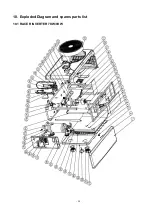
Page 93: ...90 10 Exploded Diagram and spares parts list 10 1 RACER INVERTER 7KW 9KW...
Page 96: ...93 10 2 RACER INVERTER 11KW 14KW 16KW...
Page 100: ...97 10 3 RACER INVERTER 19KW 25KW...
Page 104: ......
Page 105: ......
Page 106: ......
Page 107: ......
Page 108: ...CASH PISCINES FRANCE 13 Avenue Neil Armstrong 33700 M rignac A0165RCI02...


