background image

8. INSPECTION AND MAINTENANCE                               


Warning!  Always  clean  the  appliance  after  use.  Failure  to  clean  it  properly  may  cause 
damage to the unit or cause malfunction. 
Warning! Injuries may occur during work on teeth. Wear protective gloves. 
Before carrying out any maintenance, switch off the appliance and allow it to cool down. 
 

GENERAL MAINTENANCE 

-  Check that the tool is not damaged.


-  Check that there are no materials or objects that could be jammed on the blades.


-  Clean the body with a damp cloth or a soft brush. Remove all materials and objects that may 

obstruct ventilation.


-  Check transmission lubricant after each use or after 40 hours of operation. Replace lubricant if 

necessary.


-  Check the condition of the cutting teeth and make sure that all connections are tight. If the teeth 

are dull, contact a specialist workshop to repair them if necessary.


-  Whenever possible, clean the appliance immediately after you have finished working.


-  Clean  the  underside  of  the  housing  around  the  teeth  and  the  protective  plate  as  well  as  the 

bumper  with  a  brush  and  brush  or  a  soft  cloth  soaked  in  mild  soap  mixed  with  water.  Never 
splash with water!


-  Remove dirt and debris from teeth and transmission, use a brush or damp cloth.


-  Worn teeth make the performance bad and may cause the engine to overload; Remove them to 

clean them. Once cleaned, wipe the teeth and shaft, and apply a light coat of oil.


PERIODIC / SEASONAL MAINTENANCE 

-  After 150 hours: clean the gear housing and replace the oil.


-  After  800  hours:  Check  all  parts  of  the  tool  and  have  it  repaired  or  replaced  by  a  qualified 

technician if necessary.


-  Once a season: Grease the teeth and the tree.


-  At the end of the season, check the unit and have it serviced in a specialized workshop.


MAINTENANCE OF THE AIR FILTER 

Warning! Do not use petrol or abrasive products to clean the air filter. 

A  dirty  air  filter  prevents  air  from  entering  the  carburetor  and  prevents  proper  operation  of  the 
carburetor. Air filters must be maintained regularly: 

-  Press the buckle and remove the air filter cover, and then remove the air filter.


-  Using a mild soap solution and water to clean the air filter. Dry it.


-  Replace the air filter and cover.


9. TRANSPORTATION AND STORAGE                                     


Clean the unit thoroughly before storing.


Do not lift the machine, move it by rolling it while holding both handles.


Store the device in a clean and dry place. The machine must be turned off and cooled.


The  fuel  or  oil  may  leak  during  transport.  Secure  the  unit  properly  and  take  preventative 
measures to protect the environment from contamination.


Summary of Contents for RAC139PTIL-B

Page 1: ...ORIGINAL INSTRUCTIONS EN PETROL TILLER RAC139PTIL B USER GUIDE CAUTION Read the instructions before using the machine...

Page 2: ...DUCT DESCRIPTION 7 4 TECHNICAL DATA 7 5 ASSEMBLY 8 6 OIL AND FUEL FILLING 16 7 OPERATION 17 9 TRANSPORTATION AND STORAGE 19 10 DECLARATION OF CONFORMITY 20 11 WARRANTY 21 12 PRODUCT FAILURE 22 13 WARR...

Page 3: ...a While working always wear substantial footwear and long trousers Do not operate the equipment when barefoot or wearing open sandals b Thoroughly inspect the area where the equipment is to be used a...

Page 4: ...he motor heats up during use Make sure the engine is cool before refuelling If there is leaking fuel clean it up thoroughly and wait until it is dry before operating the engine This tool is not intend...

Page 5: ...should strike extremely hard packed soil frozen ground or buried obstacles such as large stones roots or stumps The adjustable part of the protective device shall be adjusted to the working depth of...

Page 6: ...arantee sound power level Wear safety footwear Wear protective gloves The fuel is flammable keep it away from the fire Do not add fuel while the machine is running Clutch lever STOP position Clutch le...

Page 7: ...FF lever 3 Handle bracket 4 Starter rope 5 Oil tank 6 Fuel tank 7 Air filter 8 Mudguard 9 Blades 10 Wheel 11 Drag strut depth limiter 12 Primer button The tool is also provided with 4 blades 2 extensi...

Page 8: ...ions carefully and operate every step strictly according to the instructions INSTALL THE DRAG STRUT Remove the M8 35 bolts and nuts on the drag strut of the rotary tiller Fig 2 Fig 3 and insert the dr...

Page 9: ...GHT HANDRAILS Remove the M8x30 bolts 8x 24x2 washers and M8 nuts from the tool bag Fig 9 Insert left handrail into the hole of handrail fixing seat align the hole position install the hexagon head bol...

Page 10: ...the left and right handrails by using a wrench Fig 12 INSTALL THE CLUTCH CABLE Unscrew an M8 nut among the adjustment screws of clutch cable and lead it through the lug hole of the iron block of left...

Page 11: ...g 16 Fig 17 ADJUST THE TIGHTNESS OF CLUTCH CABLE Tighten the screw of the clutch cable by hand Fig 18 and screw M8 nut to the position of small iron block to check whether the clutch cable is properly...

Page 12: ...he quick release pin Fig 22 and install the rotary blade on the shaft lever of transmission box Pay attention to the direction of casing keep the short end casing inward Fig 23 and insert the quick re...

Page 13: ...left and right auxiliary fenders Fig 26 place the auxiliary fenders under the main fenders Fig 27 Screw the M8 12 bolts into the corresponding threaded hole and tighten it with a wrench Fig 27 Instal...

Page 14: ...e upward to the corresponding hole position and screw the two bolts in and lock with a wrench Fig 31 Fasten the clutch cable and throttle cable to the left and right handrails with cable clamps Fig 28...

Page 15: ...Fig 30 Fig 31 Fig 32...

Page 16: ...e blade or drain the oil empty the fuel tank WARNING Never fill the fuel tank indoors when the engine is running or before the engine has been able to cool for at least 15 minutes after use CAUTION Do...

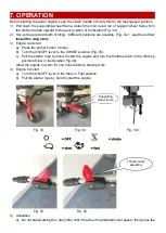
Page 17: ...ld start a Press the primer button 3 times b Turn the ON OFF lever to the CHOKE position Fig 35 c Pull the starter rope by hand to start the engine and turn the throttle switch to the Working position...

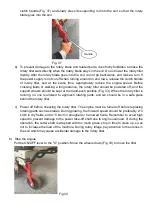
Page 18: ...kept at the hand push position Fig 33 When the rotary tiller is running no one is allowed to approach rotating parts and we should be in a safe place behind the rotary tiller c Power off before checki...

Page 19: ...d transmission use a brush or damp cloth Worn teeth make the performance bad and may cause the engine to overload Remove them to clean them Once cleaned wipe the teeth and shaft and apply a light coat...

Page 20: ...ing European Directives Machinery Directive 2006 42 EC EMC Directive 2014 30 EU Emission directive EU 2016 1628 2018 898 EU Noise Directive 2000 14 EC and 2005 88 EC Applicable harmonized standards EN...

Page 21: ...he user manual Due to our policy of continuous product improvement we reserve the right to alter or change specifications without notice Consequently the product may be different from the information...

Page 22: ...Repairs will be done by approved engine manufacturers of these manufacturers see their site http www briggsandstratton com eu fr http www honda engines eu com fr service network page jsessionid 5EE845...

Page 23: ...essary for repairs and more generally the costs related to the immobilization of the product The costs of a second opinion established by a third party following an estimate by a SWAP Europe repair st...

Page 24: ...BUILDER SAS 32 rue Aristide Berg s ZI 31270 Cugnaux France Made in PRC 2022...

Reviews: