Chapter 3 - Setup and Installation
JBOD (OmniStor 4000F)
47
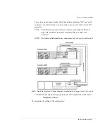
Multiple Enclosures with one or more Host(s) and HBA(s)
1
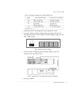
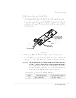
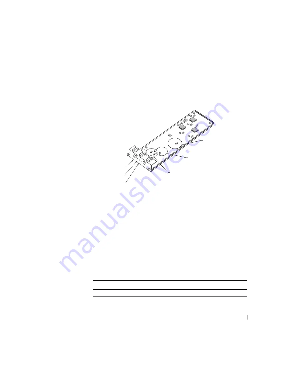
Verify the jumper (JP3) setting on the Disk IO card is set for single bus operations.
Loosen the two captive fastener screws for the Disk I/O card and remove it from the
enclosure. Locate the jumper JP3 and ensure that it is installed on one pin only. This is
the default position.
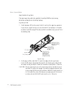
Disk I/O Card
2
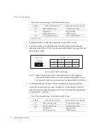
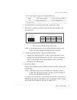
Set the jumper (JP4) on the Disk I/O card(s) to configure the bus speed mode.
Locate the JP4 jumper and position the jumper for the desired speed setting. Install
the jumper on one pin only for 2 Gb mode or install it on both pins for 1 Gb mode.
CAUTION:
The bus speed must be set to the same setting between the disk drives and
the Disk I/O card(s). For example, if you have an expansion enclosure and
you are using 2 Gb drives in both enclosures, the Disk I/O cards must be set
to 2 Gb mode. If you have 2Gb drives in one enclosure and 1 Gb drives in
another enclosure, the Disk IO cards must be set to 1 Gb mode.
Disk I/O Card Jumper Settings for the
Omni
Stor 4000F Series
JUMPER
INSTALLED BOTH PINS
INSTALLED ONE PIN (OFFSET)
JP1
Wahoo Controllers Only
* Non-Wahoo Controllers
D1
DISK I/O
D2
OK
OK
2G
Fibre Disk IO LRC
P/N 08-9-96318001
A/W Re
v-1
INST
ALL JUMPERS 1 & 2
FOR HARD
WARE
FAILURE DETECT
ADD JUMPER FOR
1G OPERA
TION
JP1
JP4
JP3
JP2
ADD JUMPER FOR
SPLIT B
US MODE
FC-AL Loop Port
Loop Status LED
2 Gb/1 Gb Mode LED
Install Jumper JP3 on both
pins for Split Bus mode, and
offset or on one pin only for
Single Bus mode.
Install Jumper JP4 on
both pins for 1Gb mode,
and on one pin only for
2 Gb mode.
Jumpers JP1 and JP2
are applicable to Wahoo
controllers only, for all
other controllers the
jumpers should be offset
or installed on one pin only.
Summary of Contents for OMNISTOR 4000f SERIES
Page 1: ......
Page 2: ......
Page 4: ......
Page 8: ...Table of Contents iv ...
Page 30: ...Chapter 1 Getting Started Audible Alarm 18 ...
Page 66: ...Chapter 3 Setup and Installation Powering Off the Storage System 54 ...


