SCADA radio network step-by-step
Building a reliable radio network for a SCADA system may not be that simple, even when you use such
a versatile and easy-to-operate device as the RipEX radio modem. The following step-by-step checklist
can help you to keep this process fast and efficient.
1.
Design your network to ensure RF signal levels meet system requirements.
2.
Calculate and estimate the network throughput and response times when loaded by your application.
3.
Perform a bench-test with 3-5 sets of RipEX's and SCADA equipment (Chapter 5,
).
4.
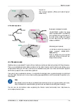
Design the addressing and routing scheme of the network (Chapter 2,
and
1
)
5.
Preconfigure all RipEX's (Section 5.4, “Basic setup”).
6.
Install individual sites
1.
Mount RipEX into cabinet (Section 6.1, “Mounting”).
2.
Install antenna (Section 6.2, “Antenna mounting”).
3.
Install feed line (Section 6.3, “Antenna feed line”).
4.
Ensure proper grounding (Section 6.4, “Grounding”).
5.
Run cables and plug-in all connectors except from the SCADA equipment (Section 4.2,
“Connectors”)
6.
Apply power supply to RipEX
7.
Test radio link quality (Section 5.5, “Functional test”).
8.
Check routing by the ping tool (the section called “Ping”) to verify accessibility of all IP ad-
dresses with which the unit will communicate.
9.
Connect the SCADA equipment
7.
Test your application
1
http://www.racom.eu/eng/products/m/ripex/app/routing.html
9
© RACOM s.r.o. – RipEX Radio modem & Router
Getting started
Summary of Contents for RipEX 1.6.0
Page 2: ......


