Chapter 2
Wiring
2.1
WaveGuide radar
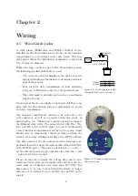
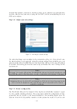
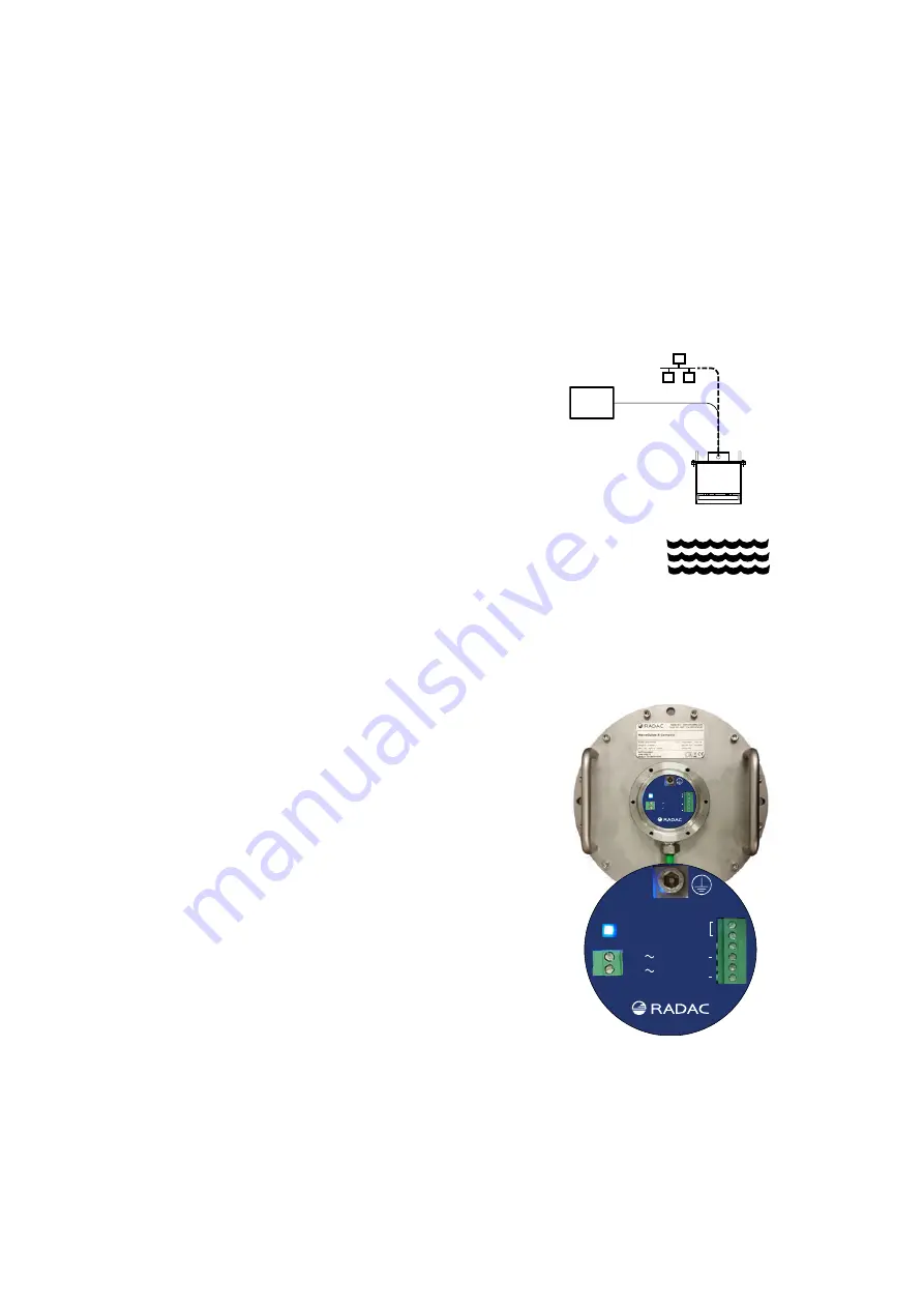
Figure 2.1: Block diagram of the
Waveguide Onboard 2 system.
A cable gland (IP68-10bar and IP69K certified) is pre-
installed on the WaveGuide sensor for use on the terminal
compartment as a watertight cable entry point. The sup-
plied gland allows the installation of insulated cables from
8 to 15 [mm] in diameter.
When selecting a cable for use with a WaveGuide system,
the following specifications must be used:
• Two wires for power transmission, the choice of power
supply will influence the diameter and insulation thick-
ness of those wires.
• Four wires for data transmission, at least satisfying
Category 5e Ethernet cable (Cat 5e) specifications.
• The cable must be shielded and can have a maximum
length of 80 [m].
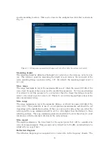
Figure 2.2: Terminal compartment
and connections.
Upon request, Radac can supply an optional cable that com-
plies with the WaveGuide system requirements for power
and data transmission.
The terminal compartment contains a six pole and a two
pole connector as well as a ground connection point, as
shown in Fig. 2.2. The six pole connector is used to connect
the Ethernet data wires. The poles labeled with Tx+, Tx-,
Rx+ and Rx- relate to RJ45 pins 1,2,3 and 6. Additionally
a reset function is implemented on the top two poles, which
should only be temporarily connected when resetting the
radar to its factory settings or setting a fixed IPV4 address.
The 2nd connector (2 pole connector) in the terminal com-
partment is used to supply the system with either 24-65VDC
or 65-240VAC power. The poles are labeled as +/~ and -/~,
yet the internal power supply operates also when the + and
- poles are switched around.
Please do take into account the voltage drop due to wire
resistance between the power supply unit and the radar, the
radar must at all times receive more than 21.0 VDC. For
this reason, to be sure to stay within the limits, at longer
distances it is advised to use a 36VDC or a 48VDC power
supply.
6
Summary of Contents for WaveGuide 5 Onboard 2
Page 1: ...WaveGuide Onboard 2 User Manual...
Page 20: ...Figure 3 8 Dashboard view 17...


